


4. HOW TO MONITOR REDUNTANT SYSTEM
4 - 3
1
PREPARATORY
PROCEDURES FOR
MONITORING
2
DEVICE RANGE
THAT CAN BE SET
3
ACCESS RANGE
FOR MONITORING
4
HOW TO MONITOR
REDUNTANT
SYSTEM
5
BUS CONNECTION
6
DIRECT
CONNECTION TO
CPU
7
COMPUTER LINK
CONNECTION
8
ETHERNET
CONNECTION
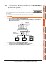
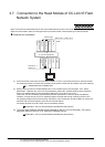
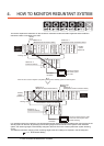
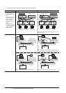
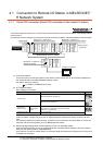
The following connection methods are available for the QCPU redundant system.
• Connection to remote I/O station in MELSECNET/H network system
(1) Direct CPU connection (Remote I/O station of MELSECNET/H network system)
4.1.1 Direct CPU connection (Direct CPU connection to the remote I/O station)
(2) Computer link connection (Serial communication module mounted on remote I/O station of MELSECNET/H
network system)
4.1.2 Computer link connection (Connection to serial communication module mounted on remote
I/O station)
(3) Ethernet connection (Ethernet module mounted on the remote I/O station of the MELSECNET/H network
system)
4.1.3 Ethernet connection (Connection to Ethernet module mounted on remote I/O station)
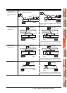
• Direct CPU connection
4.2 Direct CPU Connection
• CC-Link connection (intelligent device station)
4.3 CC-Link Connection (Intelligent Device Station)
• CC-Link connection (Via G4)
4.4 CC-Link Connection (Via G4)
• MELSECNET/H connection, MELSECNET/10 connection (Network system)
4.5 MELSECNET/H and MELSECNET/10 Connections (Network Systems)
• CC-Link IE Controller Network connection (Network system)
4.6 CC-Link IE Controller Network Connection (Network System)
• Ethernet connection
4.7 Ethernet Connection
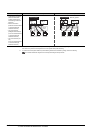
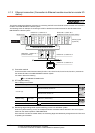
• Connection to the redundant type extension base unit
(1) Computer link connection (Serial communication module mounted on the redundant type extension base unit)
4.8.1 Computer link connection (Connection to the Serial communication module mounted on the
redundant type extension base unit)
(2) Ethernet connection (Ethernet module mounted on the redundant type extension base unit)
4.8.2 Ethernet connection (Connection to the Ethernet module mounted on redundant type
extension base unit)
(3) CC-Link connection (intelligent device station) (CC-Link module mounted on the redundant type extension base
unit)
4.8.3 CC-Link connection (intelligent device station) (Connection to the CC-Link module
mounted on redundant type extension base unit)
(4) CC-Link connection (Via G4) (CC-Link module mounted on the redundant type extension base unit)
4.8.4 CC-Link connection (Via G4) (Connection to the CC-Link module mounted on redundant
type extension base unit)
For details of PLC CPUs that can be monitored in each connection method of GOT, refer to the following.
Monitorable controllers of each chapter