


8. ETHERNET CONNECTION
8.4 PLC Side Setting
8 - 21
1
PREPARATORY
PROCEDURES FOR
MONITORING
2
DEVICE RANGE
THAT CAN BE SET
3
ACCESS RANGE
FOR MONITORING
4
HOW TO MONITOR
REDUNTANT
SYSTEM
5
BUS CONNECTION
6
DIRECT
CONNECTION TO
CPU
7
COMPUTER LINK
CONNECTION
8
ETHERNET
CONNECTION
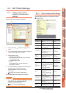
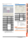
[Controller Setting] and [Ethernet] of GT
Designer3
POINTPOINTPOINT
(1) [Controller Setting] and [Ethernet] of GT
Designer3
For [Controller Setting] and [Ethernet] of GT
Designer3, refer to the following.
8.3.1 Setting communication interface
(Communication settings)
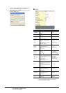
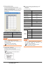
(2) Ethernet setting
When connecting Built-in Ethernet port QCPU or
LCPU to a GOT, the settings items for the network
No. and station No. do not exist at the PLC side.
However, these virtual values must be set on the
GOT side. Therefore, set the network No. and
station No.
Therefore, set the network No. and station No.
Set the network No. that is not existed on the
network system and any station No..
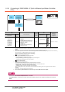
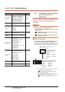
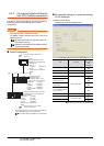
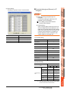
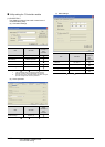
(3) Controller setting
(4) Ethernet setting
*1 Set the same value as that of GOT N/W No.
*2 Set a value different from that of GOT PLC No.
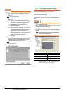
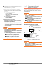
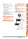
Checking communication state of Connecting
to Built-in Ethernet port CPU
(1) When using the Command Prompt of Windows
.
Execute a Ping command at the Command Prompt of
Windows
.
(a) When normal communication
C:\>Ping 192.168.3.39
Reply from 192.168.3.2: bytes=32 time
<10ms TTL=32
(b) When abnormal communication
C:\>Ping 192.168.3.39
Request timed out.
(2) When abnormal communication
At abnormal communication, check the followings and
execute the Ping command again.
• Cable connecting condition
• Confirmation of switch and network parameter setting
• Operation state of PLC CPU (faulty or not)
• The IP address of Built-in Ethernet port CPU specified
in the ping command
POINTPOINTPOINT
Ethernet diagnostics of GX Developer
Ethernet diagnostics of GX Developer is available to a
Ping test from the PLC.
For details of Ethernet diagnostics of GX Developer,
refer to the following manual.
QCPU User's Manual (Hardware Design,
Maintenance and Inspection)
MELSEC-L CPU Module User's Manual
(Hardware Design, Maintenance and
Inspection)
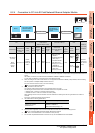
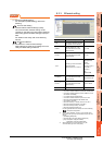
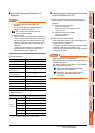
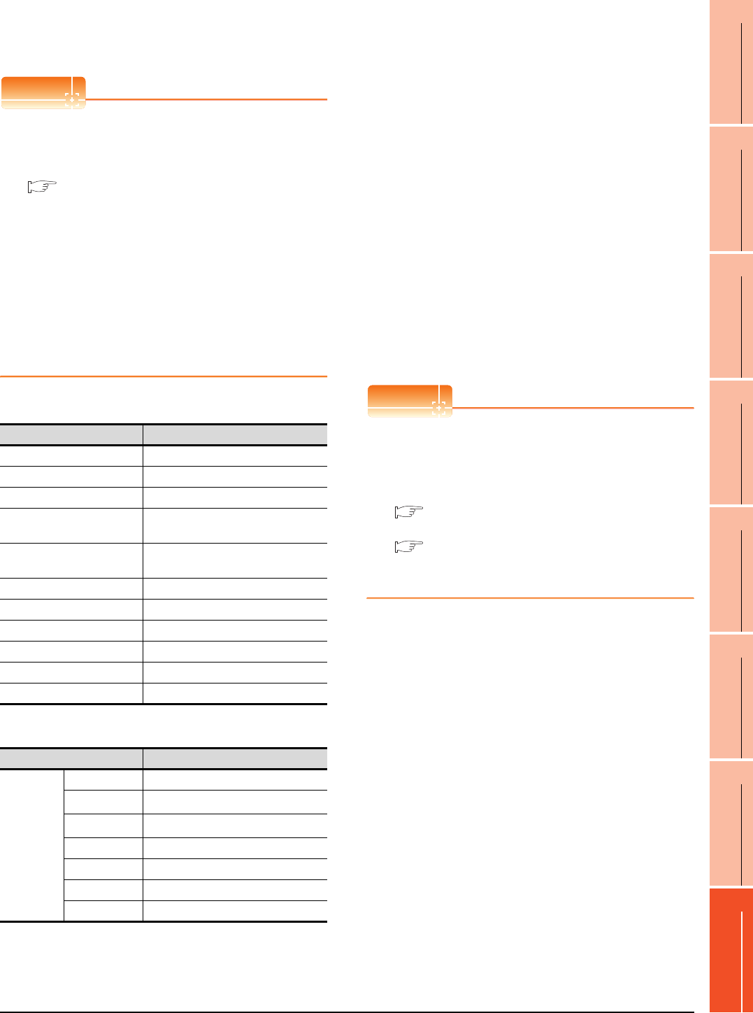
Item Set value (Use default value)
GOT NET No. 1
GOT PLC No. 1
GOT IP Address 192.168.3.1
GOT Port No.
(Communication)
5001
GOT Port No.
(Ethernet Download)
5014
Default Gateway 0.0.0.0
Subnet Mask 255.255.255.0
Retry 3times
Startup Time 3sec
Timeout Time 3sec
Delay Time 0ms
Item Set value
Ethernet
setting No.1
Host *
N/W No.
1
*1
PLC No.
2
*2
Type QnUDE(H), LCPU
IP address 192.168.3.39
Port No. 5006 (fixed)
Communication UDP (fixed)