


Chapter 6 6-15
Removing and Replacing Parts
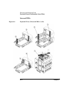
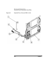
Exploded Views of Replaceable Parts (FRUs)
Errors and Troubleshooting
Removing/Replacing Parts
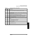
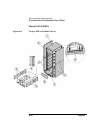
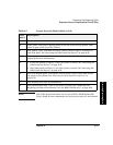
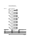
Table 6-6 Description of Internal FRUs (2 of 2)
Call-
out #
FRU
ID
Description
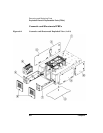
1 65 Display cable (included in cable kit). Access this part by removing the
library side panels. The display cable needs to be threaded
underneath the right door tray rail to connect to the motherboard (see
Figure 6-25 on page 6-49). Do not connect the display cable on all
levels; only connect the cable located on the level with the display.
2 N/A Power switch cable (included in cable kit). Access this part by
removing the chin plate on the front and at the bottom of the library
and the right side panel on the lowest library level.
3 N/A Mailslot solenoid assembly: Two #4-40 x .375 T-10 screws secure this
part to the inside edge of the library. Remove the library side panels
to access this part.
4 N/A Magazine lock harness cable (included in cable kit), see Figure 6-29
on page 6-53. Access this part by removing the library side panels.
Secure the cable to the side of the library chassis to ensure it does not
become damaged.
5 N/A Interconnect cable that connects multi-level libraries (included in
cable kit, see Figure 6-25 on page 6-49).
6 48 Chassis fan: Remove all cards from the back of the library. Remove
the four 6-32 T-15 screws that secure the fan inside the back of the
library.
7 3 Motherboard: Uses #4-40 x .625 screws to attach (see page 6-48 for
more information).