


Chapter 6 6-11
Removing and Replacing Parts
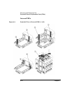
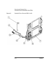
Exploded Views of Replaceable Parts (FRUs)
Errors and Troubleshooting
Removing/Replacing Parts
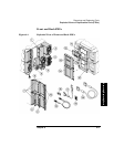
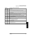
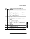
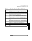
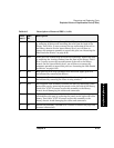
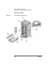
Table 6-4 Description of Cosmetic and Sheetmetal FRUs (2 of 2)
Call-out # Description
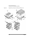
1 Library top cover for Model 2/20 (see Figure 6-12 on page 6-30). Includes
eight #4 - 40 x .25 screws to attach.
2 Bezel chin for the lowest library level. Uses 6-32 machine screws to attach.
3 Forehead for library Model 4/40 (see Figure 6-12 on page 6-30). Installed at
the top of the library with four 10-24 T-25 screws.
4 Bezel chin. See “Removing and Replacing the Front Panel Display” on
page 6-63. Uses 6-32 machine screws to attach.
5 Forehead for library Models 6/60 and 12/140 (see Figure 6-12 on
page 6-30). Installed at the top of the library with four 10-24 T-25 screws.
6 Lifting strap (used to guide libraries into a rack). Uses 10-24 x .50 screws
to attach.
7 Lifting strap (used to guide libraries into a rack). Uses 10-24 x .50 screws
to attach.
8 Vertical lift cover for multi-level libraries (see Figure 6-12 on page 6-30).
Installed at the top of the library with two 10-24 x .50 screws.
9 Standalone feet. Includes four 10-24 x .50 screws to attach.
10 Standalone cover assembly for Model 2/20: Uses #10-24 x .625 screws to
attach.