


Figures
xvi
Figure 2-30. Latch Stops . . . . . . . . . . . . . . . . . . . . . . . . . . . . . . . . . . . . . . . . . . . . . . 2-50
Figure 3-1. Model 12/140 Home Screen . . . . . . . . . . . . . . . . . . . . . . . . . . . . . . . . . . . 3-3
Figure 3-2. Status Bar from Main Menu Screen . . . . . . . . . . . . . . . . . . . . . . . . . . . . 3-4
Figure 3-3. Menu Nesting . . . . . . . . . . . . . . . . . . . . . . . . . . . . . . . . . . . . . . . . . . . . . . 3-6
Figure 3-4. Removing/Replacing a Magazine . . . . . . . . . . . . . . . . . . . . . . . . . . . . . . . 3-9
Figure 3-5. Loading Ultrium Tapes into a Magazine . . . . . . . . . . . . . . . . . . . . . . . . 3-10
Figure 3-6. Loading DLT Tapes into a Magazine . . . . . . . . . . . . . . . . . . . . . . . . . . . 3-11
Figure 4-1. Mailslot Door. . . . . . . . . . . . . . . . . . . . . . . . . . . . . . . . . . . . . . . . . . . . . . . 4-7
Figure 5-1. Using the Soft Error Log . . . . . . . . . . . . . . . . . . . . . . . . . . . . . . . . . . . . 5-18
Figure 5-2. Leader in Correct Position and Door Tab . . . . . . . . . . . . . . . . . . . . . . . 5-38
Figure 5-3. Main Diagnostics Tree . . . . . . . . . . . . . . . . . . . . . . . . . . . . . . . . . . . . . . 5-41
Figure 5-4. LED Diagnostics Tree. . . . . . . . . . . . . . . . . . . . . . . . . . . . . . . . . . . . . . . 5-42
Figure 5-5. Electronic Diagnostics Tree . . . . . . . . . . . . . . . . . . . . . . . . . . . . . . . . . . 5-43
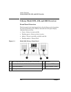
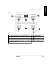
Figure 6-1. Exploded View of Front and Back FRUs . . . . . . . . . . . . . . . . . . . . . . . . 6-5
Figure 6-2. Cosmetic and Sheetmetal Exploded View (1 of 2) . . . . . . . . . . . . . . . . . . 6-8
Figure 6-3. Exploded View of Cosmetic and Sheetmetal FRUs (2 of 2) . . . . . . . . . 6-10
Figure 6-4. Exploded View of Internal FRUs (1 of 2) . . . . . . . . . . . . . . . . . . . . . . . . 6-12
Figure 6-5. Exploded View of Internal FRUs (2 of 2) . . . . . . . . . . . . . . . . . . . . . . . . 6-14
Figure 6-6. Unique FRUs for Model 12/140 . . . . . . . . . . . . . . . . . . . . . . . . . . . . . . . 6-16
Figure 6-7. Library Card Positions . . . . . . . . . . . . . . . . . . . . . . . . . . . . . . . . . . . . . . 6-20
Figure 6-8. Ribbon Cable and Connector . . . . . . . . . . . . . . . . . . . . . . . . . . . . . . . . . 6-24
Figure 6-9. Removing a Drive . . . . . . . . . . . . . . . . . . . . . . . . . . . . . . . . . . . . . . . . . . 6-25
Figure 6-10. Installing a Drive Module. . . . . . . . . . . . . . . . . . . . . . . . . . . . . . . . . . . 6-26
Figure 6-11. Removing the Stop Bracket for Models 4/40 and 6/60 . . . . . . . . . . . . 6-29
Figure 6-12. Access to the Transport Assembly . . . . . . . . . . . . . . . . . . . . . . . . . . . . 6-30
Figure 6-13. Removing the Transport Assembly . . . . . . . . . . . . . . . . . . . . . . . . . . . 6-31
Figure 6-14. Guide Blocks . . . . . . . . . . . . . . . . . . . . . . . . . . . . . . . . . . . . . . . . . . . . . 6-32
Figure 6-15. Transport Assembly Position . . . . . . . . . . . . . . . . . . . . . . . . . . . . . . . . 6-33
Figure 6-16. Removing the Cabinet Side Panels . . . . . . . . . . . . . . . . . . . . . . . . . . . 6-36
Figure 6-17. Removing the Library Side Panels. . . . . . . . . . . . . . . . . . . . . . . . . . . . 6-37
Figure 6-18. Removing the Interconnect Cable . . . . . . . . . . . . . . . . . . . . . . . . . . . . 6-39
Figure 6-19. Removing the Shipping Brackets. . . . . . . . . . . . . . . . . . . . . . . . . . . . . 6-40
Figure 6-20. Removing the Retainer Brackets . . . . . . . . . . . . . . . . . . . . . . . . . . . . . 6-41
Figure 6-21. Removing the Transport Assembly . . . . . . . . . . . . . . . . . . . . . . . . . . . 6-42
Figure 6-22. Transport Assembly Position . . . . . . . . . . . . . . . . . . . . . . . . . . . . . . . . 6-43
Figure 6-23. Checking the Module Alignment . . . . . . . . . . . . . . . . . . . . . . . . . . . . . 6-44