


INTERNAL SPECIFICATIONS
89
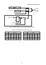
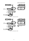
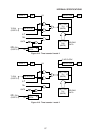
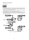
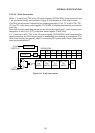
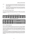
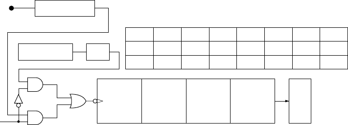
4.5.2.5.6 32-bit timer mode
When “1” is set in bit 6 (T32) of the I/O control register (IOCON 0F8H), timer/counters 0 and
1 are connected serially as indicated in Figure 4-18 to become a 32-bit timer/counter.
This 32-bit timer/counter is started by the following procedure. First, “0” is set in TR0, TR1,
TF0, and TF1 of the timer control register (TCON 88H) to stop the timer/counter and reset the
timer flag.
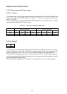
Next timer/counter preset data values are set in timer/counters 0 and 1, and a counter clock
designation is set in bit 2 (C/T) of the timer mode register (TMOD 89H).
If “1” is then set in bit 6 (T32) of the 1/0 control register (IOCON 0F8H) after completing the
above procedure, the 32-bit timer/counter is established and counting is commenced. This
32-bit timer/counter is especially useful in cancelling CPU power down mode. (See power
down mode cancellation.)
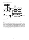
Figure 4-18 32-bit timer/counter
Q0-----Q7
TL0
(8BITS)
XTAL 1 ÷
12
DETECTOR
T0 PIN
(PORT 3.4)
C/
T
(TMOD bit2)
Q0-----Q7
TH0
(8BITS)
Q0-----Q7
TL1
(8BITS)
Q0-----Q7
TH1
(8BITS)
TF1
76543210
— T32
SERR
IZC
P3HZ P2HZ P1HZ
ALF
•
IOCON [0F8H]