


INTERNAL SPECIFICATIONS
61
4.3 lnternal Data Memory (RAM) Operating Procedures
4.3.1 Internal data memory indirect addressing
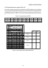
Operation of the internal data memory indirect increment instruction is described here as an
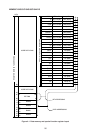
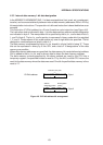
example. This instruction (INC @Rr) is a 1-byte 1-machine cycle instruction (see Figure 4-
4). The indirect address register is specified by instruction code bit 0 data r where r denotes
either register 0 or 1 in the register group specified by PSW RS0 and RS1 bank data. Register
0 is specified when the r data is 0, and register 1 is specified when the data is 1.
When this instruction is executed, register data is read from the specified register 0 or 1, and
the read out register data is written into the data pointer for the data memory.
The data memory contents specified by the data pointer are read by the CPU into a temporary
register. Then a subsequent increment (+1) by the ALU is followed by a return to the data
memory at the address where the data were read out. In this way, the contents of the data
memory at the address specified by the contents of R0 or R1 are incremented.
0000011r
76543210
Instruction (OP)
code portion
Register
designation portion
INC @Rr: Byte 1
Figure 4-4 INC @Rr bit arrangement