


INTERNAL SPECIFICATIONS
125
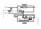
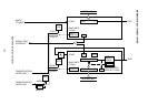
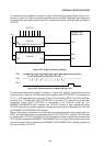
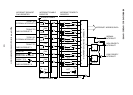
An output extension example is shown in Figure 4-39 and the corresponding timing chart is
shown in Figure 4-40. After output data has been written into SBUF and the output sequence
completed, the latch pulse output from PX.X is obtained and the 74LS164 data is shifted to
74LS373.
PX.X
MSM80C154S
MSM83C154S
RXD
TXD
8Q 7Q 6Q 5Q 4Q 3Q 2Q 1Q
8D 7D 6D 5D 4D 3D 2D 1D
OC G
74LS373
QHQGQF QEQDQCQBQA
CLK CK
74LS164
BA
OUTPUT
VCC
Figure 4-39 Output extension example
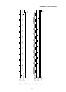
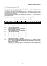
PX.X
TXD
RXD
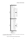
Figure 4-40 Output extension example timing chart
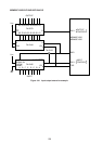
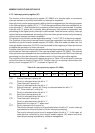
An input/output extension example is shown in Figure 4-41 and the corresponding timing
chart is shown in Figure 4-42. When input data is applied, INPUT CONTROL is changed from
“0” to “1”, and the parallel input is latched. This is then followed by REN=1 and RI=0 settings,
and shift in of 74LS165 data. INPUT CONTROL is returned to “0” after the input has been
completed. Since INPUT CONTROL is connected to the 74LS126 control pin, the
MSM80C154S/MSM83C154S switches the 74LS126 output to high impedance when
74LS165 input data is not being applied, thereby preventing collision between the 74LS126
and MSM80C154S/MSM83C154S outputs.
When output data is generated, and the output is completed after writing output data into
SBUF, an output latch pulse is generated from OUTPUT CONTROL, and the 74LS164 data
is transferred to 74LS373. Although the 74LS164 data is changed to parallel input data when
74LS165 data is passed to MSM80C154S/MSM83C154S, an output latch pulse is generated
only when output data is obtained from MSM80C154S/MSM83C154S, thereby preserving
the correct data in 74LS373.