


INTERNAL SPECIFICATIONS
137
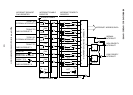
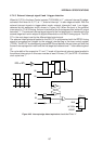
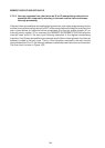
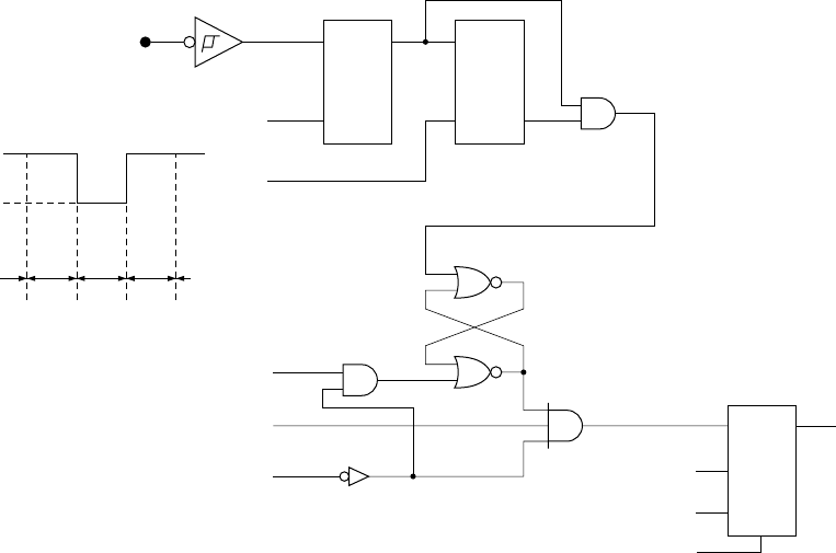
4.7.4.3 External interrupt signal 0 and 1 trigger detection
When bit 0 (IT0) in the timer Control register (TCON 88H) is “1”, external interrupt 0 is edge-
activated. And when bit 2 (IT1) is “1”, external interrupt 1 is also edge-activated. With the
external interrupt signals in trigger-detect mode, external interrupts 0 and 1 are trigger-
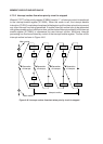
detected by the equivalent circuit shown in Figure 4-48. When the level of the external
interrupt pin is “0” at S5 timing, the level is latched at the first stage and the latched Q output
becomes “1”. The external interrupt signal stored in the first stage latch is transferred to the
second stage latch and is subject to digital differentiation until the S3 timing signal. The RS-
F/F in the next stage is set by the differentiated output signal.
The external interrupt signal applied to the RS-F/F is synchronized with the M2·S3 timing
signal to be applied as a trigger for the external interrupt flag in the timer control register
(TCON). The RS-F/F is subsequently reset at M2·S4 and waits for the next interrupt. Note that
the next interrupt signal is invalid until the first stage latch detects level “1” after detecting level
“0”.
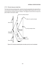
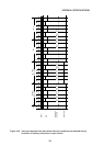
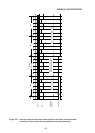
The cycle width of the respective “0” and “1” levels of the external interrupt signal applied to
the external interrupt pin in this case must be at least 12 times (12T) the XTAL1·2 oscillator
clock cycle time T.
QS
L
1
0
12T 12T 12T
QD
L
S5
INT
0 or
INT
1
IE0 or 1
Q
D
L
S3
M2
S3
S4
D
W TCON
BUS
R
RESET
Figure 4-48 lnterrupt edge detect equivalent circuit for IT bit “1”