


INTERNAL SPECIFICATIONS
119
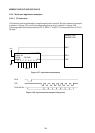
4.6.3.4 Mode 3
4.6.3.4.1 Outline
Mode 3 is another 11-bit frame UART mode (with one start bit, eight data bits, one multi-
purpose data bit, and one stop bit). Whereas the baud rate is 1/64th or 1/32nd of the
fundamental oscillator frequency in mode 2, the mode 3 baud rate can be freely selected
according to the timer/counter 1 or timer/counter 2 setting. Apart from the ability to vary the
baud rate, mode 3 is identical to mode 2.
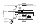
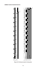
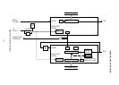
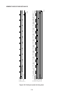
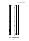
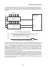
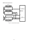
A block diagram of the serial port in mode 3 is shown in Figure 4-35, and the operational timing
chart is given in Figure 4-36.
4.6.3.4.2 Mode 3 baud rate
As in mode 1, the timer/counter 1 or timer/counter 2 overflow can be set as the baud rate clock
source in mode 3 by independent TCLK and RCLK setting for the transmit and receive
circuits.
Where the baud rate is determined by the timer/counter 1 overflow, baud rate is determined
by the overflow frequency and SMOD value according to the following equations.
B = fTC1 ×
2
1
× (SMOD=0)
B = f
TC1 × (SMOD=1)
16
1
16
1
Where B is the baud rate and fTC1 is the timer/counter 1 overflow frequency.
When timer/counter 1 is used as a timer in auto reload mode (mode 2), the baud rate is
determined by the following equations.
B = fOSC ×
256-DTH1
1
× (SMOD=0)
(SMOD=1)
12
1
2
1
×
16
1
×
B = f
OSC ×
256-DTH1
1
×
12
1
×
16
1
where B is the baud rate, fOSC the fundamental oscillator (XTAL1·2) frequency, and DTH1 the
TH1 contents (expressed in decimal).
Where the timer/counter 2 overflow serves as the baud rate clock source, the baud rate is
determined by the overflow frequency irrespective of the SMOD value.
When timer/counter 2 is used as a counter, the baud rate is determined by the following
equation.
B = fT2 ×
65536-DRCAP2
1
×
16
1
where B is the baud rate, fT2 the frequency of the clock applied to the T2 pin, and DRCAP2 the
contents of RCAP2L and RCAP2H (expressed in decimal).
Or if timer/counter 2 is used as a timer, the baud rate is determined by the following way.