


MSM80C154S/83C154S/85C154HVS
98
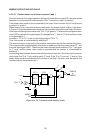
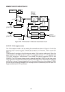
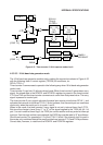
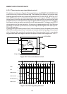
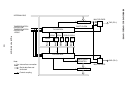
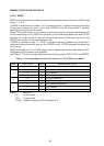
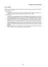
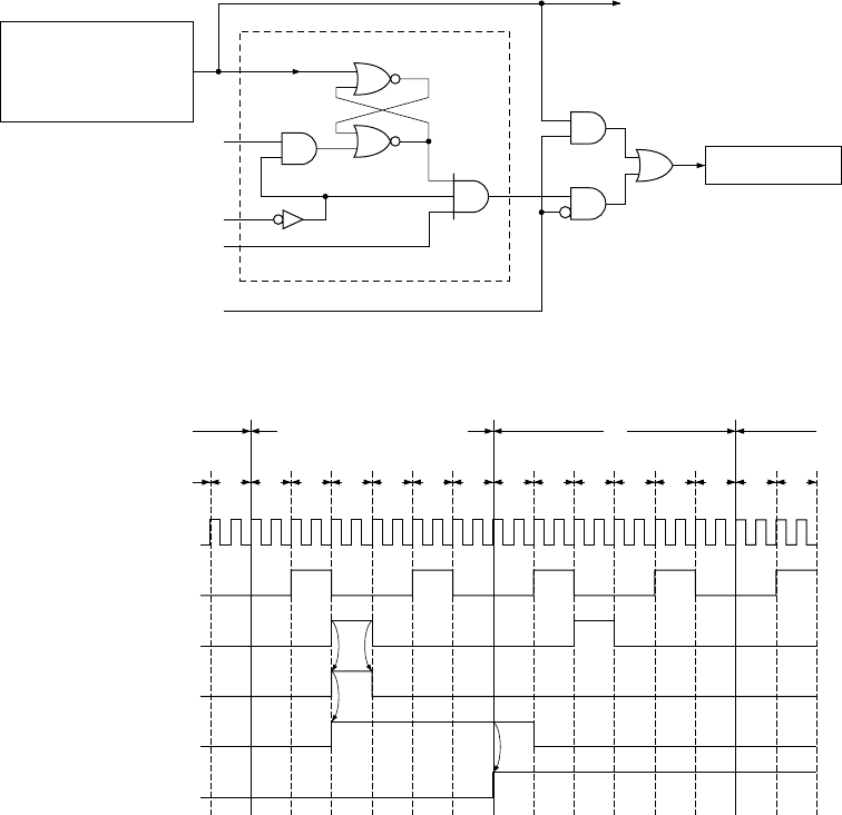
4.5.3.5 Timer/counter carry signal detector circuit
The detector circuit shown in Figure 4-25 is inserted between the MSM80C154S/ MSM83C154S
timer/counter carry output and the timer flag. The purpose of this detector is to prevent timer
flags being set by the timer carry signal during execution of OR, AND, EOR, RESET bit, SET
bit, or MOV bit instruction on the contents of the timer control register (TCON), and thereby
prevent loss of timer flags by manipulated data by the time execution of instruction has been
completed. Hence, even if a timer carry signal is generated during execution of an instruction,
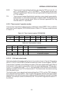
that flag will not be set while the instruction is still being executed. The flag is set at M2·S1
during execution of the next instruction. If a timer carry is generated during M1 thru M3 when
executing a 4-machine cycle instruction, the timer flag is set during M3 or M4. See Figure 4-
26 for the time chart.
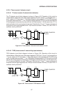
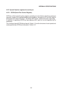
In case of driving the timer/counters 0 and 1 with the external clock in the power down mode
(PD, HPD), timer/counters 0 and 1 contents are incremented by falling edge of the external
clock. However, after counting the maximum value of timer/counters 0 and 1, carry signals
are generated and timer flags are set when the external clock level changes from “0” to “1“.
S2
PD & HPD
S1
M2
Timer flag
DETECTOR
S I/O CLOCK
Timer/counter carry
Figure 4-25 Timer/counter detector circuit
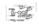
Figure 4- 26 Timer flag setting time chart
S1 S2 S3 S4 S5 S6
MACHINE CYCLE END
S1 S2 S3 S4 S5 S6
M1
S1
XTAL1
1
0
ALE
1
0
TIMER COUNT
1
0
DETECTOR OUT
1
0
TIMER FLAG
1
0
TIMER CARRY
1
0
S2S6