


INPUT/OUTPUT PORTS
203
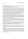
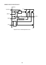
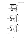
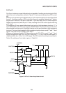
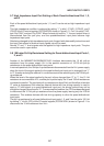
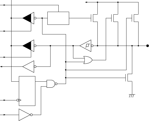
5.5 Port 3
Port 3 can function as a quasi-bidirectional port capable of handling input and output of 8-bit
data in the circuit configuration outlined in Figure 5-10, and can also be used as a CPU control
pin.
When port 3 is used as a quasi-bidirectional port, all functions are identical to those described
for port 1. And when used as a CPU control pin, the port is used after first setting “1” data in
the port latch. Note that if the port is used with “0” port latch data, the CPU control signal is
ANDed (logical product) with the port “0” data, resulting in the CPU control signal remaining
at “0” level.
To change port 3 from a quasi-bidirectional input port to a high impedance input port, “1” is
set in bit 3 (P3HZ) of the I/O control register (IOCON 0F8H). The output driver circuit is thus
disconnected from the port pin (floating pin status) and the port becomes a high impedance
input port. The signal levels applied to high impedance input ports are normal “0” and “1” level
signals. The pins cannot be used in open status.
When port outputs are floated in CPU power down mode (PD, HPD), normal “0” and “1” level
signals are applied to pins 2 thru 5 of port 3, and pins 0, 1, 6, and 7 may be either open, or
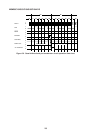
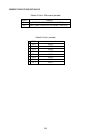
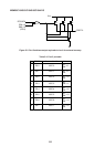
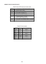
undefined within the –0.5 to VCC+0.5V range. The CPU control function pins are listed in
Table 5-5, and the port 3 pin table is given in Table 5-6.
QD
READ
INTERNAL
BUS
WP3
MODIFY
QD
C
CONTROL
P1
VCC
P2 P3
PORT 3
N
DATA OUT
DATA IN
Figure 5-10 Port 3 internal equivalent circuit