


INTERNAL SPECIFICATIONS
115
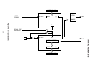
4.6.3.3 Mode 2
4.6.3.3.1 Outline
Mode 2 is an 11-bit frame UART mode (with one start bit, eight data bits, one multipurpose
data bit, and one stop bit) where the baud rate is 1/64th or 1/32nd of the fundamental oscillator
(XTAL1·2) frequency.
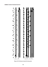
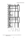
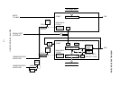
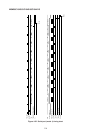
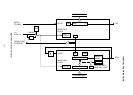
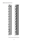
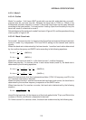
A block diagram of the serial port in mode 2 is shown in Figure 4-33, and the operational timing
chart is given in Figure 4-34.
4.6.3.3.2 Mode 2 baud rate
Since the fundamental oscillator frequency divided by two serves as the baud rate clock
source in mode 2, the baud rate is determined by the SMOD value according to the following
equations.
B = fOSC ×
2
1
×
B = f
OSC ×
16
1
2
1
×
16
1
2
1
×
(SMOD=0)
(SMOD=1)
where B is the baud rate and fOSC the fundamental oscillator (XTAL1·2) frequency.
4.6.3.3.3 Mode 2 transmit operation
The transmit basic clock (TXCLOCK in Figure 4-34) is obtained from a hexadecimal free-run
counter overflow where the frequency of 1/2XTAL1·2 (fundamental oscillator frequency
divided by 2) divided by 2 (when SMOD=0) or the 1/2XTAL1·2 frequency (when SMOD=1)
is used as the clock.
Transmission is commenced when transmit data is written in SBUF. The start bit, the eight
SBUF data bits (with the LSB first), TB8, and the stop bit are transmitted sequentially from
the TXD synchronized with the basic clock.
As soon as the TB8 output has been completed, the transmit circuit is initialized, and the T1
flag is set at the first M1·S3 after the completion of that output.
4.6.3.3.4 Mode 2 receive operation
The receive circuit timing is generated by a hexadecimal counter overflow where the
frequency of 1/2XTAL1·2 (fundamental oscillator frequency divided by 2) divided by 2 (when
SMOD=0) or the 1/2XTAL1·2 frequency (when SMOD=1) is used as the clock, and the input
data received from the RXD is bit synchronized. That is, at the same time that reception is
started following input of the start bit, the hexadecimal counter commences to count up, and
with one complete round of the hexadecimal counter corresponding to one bit of received
data, reception is continued by the receive circuit. Therefore, the reception data baud rate
must be equal to the period of a single round of the hexadecimal counter.
The RXD change from “1” to “0” is regarded as the beginning of the start bit where reception
is commenced.