


MSM80C154S/83C154S/85C154HVS
146
4.8 CPU “Power Down”
4.8.1 Outline
Since the internal MSM80C154S/MSM83C154S circuits have been designed as completely
static circuits, all internal information (register data) is preserved if XTAL1·2 oscillation is
stopped.
This feature is utilized to incorporate a fuller range of power down modes.
In idle mode (IDLE) where “1” is set in bit 0 (IDL) of the power control register (PCON),
XTAL1·2 operation is continued but CPU operations are stopped. In soft power down mode
where “1” is set in bit 1 (PD) of the power control register (PCON), XTAL1·2 operation and
CPU operations are both stopped.
And in hard power down mode where “1” is set in advance in bit 6 (HPD) of the power control
register (PCON), XTAL1·2 and CPU operations are stopped when the level of the power
failure detect signal applied to the HPDI pin (P3.5) is changed from “1” to “0”.
If “1” is set in bit 0 (ALF) of the I/O control register (IOCON 0F8H) prior to activation of soft
and hard power down modes where CPU and XTAL1·2 operations are stopped, the port 0,
1, 2, and 3 outputs can be floated.
CPU power down modes can be released (CPU start-up) by CPU resetting, interrupt
generation, and interrupt source signal generation.
Execution can be recommenced from address 0, resumed from the interrupt address or from
the next address after the power down setting instruction.
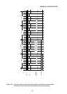
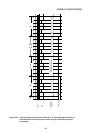
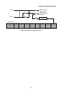
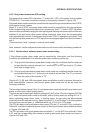
4.8.2 Idle mode (IDLE) setting
Idle mode is set when “1” is set in bit 0 (IDL) of the power control register (PCON 87H). The
circuit connections involved in this setting are shown in Figure 4-53.
The idle mode cancellation conditions can be set through manipulation of bit 5 (RPD) of the
power control register. When “0” is set in RPD, idle mode cannot be cancelled by the interrupt
signal if the corresponding interrupt enable bit has not been set. And if “1” is set in RPD, idle
mode is cancelled by setting the interrupt flag and the program is executed from the next
address of the idle mode setting instruction, even when the corresponding interrupt enable
bit is not set.
In idle mode, the supply of clocks to the CPU control section is stopped and CPU operations
are halted. But since XTAL1·2 operations are maintained, the serial port, interrupt circuits,
and timer/counters 0, 1, and 2 remain operative.
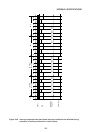
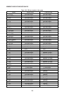
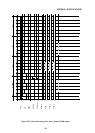
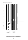
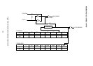
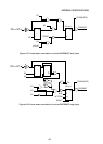
The CPU pin status during idle mode is outlined in Table 4-23, and the corresponding time
charts for starting idle mode are shown in Figures 4-54 and 4-55.