


MSM80C154S/83C154S/85C154HVS
94
XTAL 1 ÷
12
S3
DETECTOR
T2
[PORT 1.0]
Q0------Q7
TL2
8 BIT
C
RCAP2L
Q0------Q7
TH2
8 BIT
C
RCAP2H
DETECTOR
T2EX
[PORT 1.1]
TR2
EXEN2
DETECTOR
DETECTOR
TF2
EXF2
TIMER 2
INTERRUPT
RCLK=0
TCLK=0
CP/
RL2
=0
C/
T2
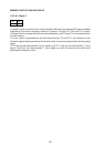
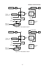
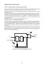
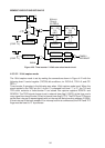
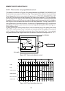
Figure 4-20 Timer/counter 2 16-bit auto reload mode circuit
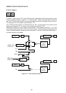
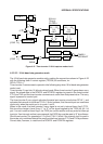
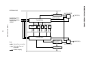
4.5.3.3.2 16-bit capture mode
The 16-bit capture mode is set by making the connections shown in Figure 4-21 with the
following timer 2 control register (T2CON) bit conditions, viz. RCLK=0, TCLK=0, and CP/
RL2=1.
Timer/counter 2 operates in the following way when 16-bit capture mode is set. When the
signal applied to the T2EX pin (bit 1 of port 1) is changed from level “1” to “0”, the TL2 and
TH2 count contents of timer/counter 2 are stored into capture registers RCAP2L and
RCAP2H. The T2EX signal change is set in external timer flag 2 (EXF2) at this time, and a
carry signal from timer/counter 2 is set in internal timer flag 2 (TF2). The EXF2 and TF2 serve
as the timer interrupt 2 request signals with an interrupt call being made to address 43 (2BH)
if timer interrupt 2 has been enabled. If an interrupt routine is commenced, the EXF2 and TF2
flags must be reset to “0” by software.