


INTERNAL SPECIFICATIONS
111
B = fOSC ×
65536-DRCAP2
1
×
16
1
2
1
×
where B is the baud rate, fOSC the fundamental frequency (XTAL1·2), and DRCAP2 the
contents of RCAP2L and RCAP2H (expressed in decimal).
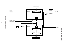
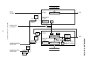
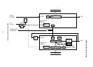
4.6.3.2.3 Mode 1 transmit operation
The transmit basic clock (TXCLOCK in Figure 4-31) is obtained from the overflow of a
hexadecimal free-run counter where the timer/counter 1 or timer/counter 2 overflow is used
as the clock.
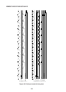
Transmission is commenced when transmit data is written in SBUF.
The start bit, the eight SBUF data bits (with the LSB first), and the stop bit are transmitted
sequentially from TXD synchronized with the basic clock.
As soon as output of the eight data bits has been completed, the transmit circuit is initialized,
and the T1 flag is set at the first M1·S3 after the completion of that output.
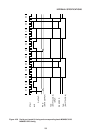
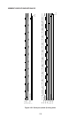
4.6.3.2.4 Mode 1 receive operation
The receive circuit timing is generated by a hexadecimal counter which uses the timer/
counter 1 or timer/counter 2 overflow as the clock, and the input data received from RXD is
bit synchronized. That is, at the same time that reception is started following input of the start
bit, the hexadecimal counter commences to count up, and with one complete round of the
hexadecimal counter corresponding to one bit of received data, reception is continued by the
receive circuit.
The RXD change from “1” to “0” is regarded as the beginning of the start bit for commence-
ment of reception.
When this “1” to “0” RXD change is detected, the hexadecimal counter which had been
stopped in reset status commences to count up. When the hexadecimal counter is in state
7, 8, and 9, the start bit is sampled, and is accepted as valid if at least two of the three sampled
values are “0”, thereby enabling data reception to continue. If two or three of the sampled
values are “1”, the start bit becomes invalid, and the receive circuit is initialized when the
hexadecimal counter reaches state 10.
The reception data is sampled when the hexadecimal counter is in state 7, 8, and 9, and the
more common value of the three sampled values is read sequentially as data into the input
shift register.
If the hexadecimal counter is in state 10 during the period of the next bit (that is, the stop bit)
after the eight bits of data have been received, and if the conditions stated below are satisfied,
the input shift register data (the LSB being read first) is loaded into SBUF, and the sampled
stop bit is read into RB8, thereby initializing the receive circuit. The RI flag is set at the first
M1·S3 after that.
Conditions: (1) RI=“0”
(2) SM2=“0”, or SM2=“1” and sampled stop bit=“0”
If the above conditions are not satisfied, the received data is disregarded, and the receive
circuit is initialized without change to the SBUF, RB8, and RI flags.
Since the receive circuit is double buffered (input shift register and SBUF), processing of the
previous receive data may be completed within the interval up to the stop bit period of the next
frame.