


MSM80C154S/83C154S/85C154HVS
78
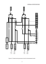
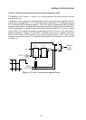
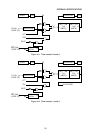
4.5.2.3 Timer/counter 0 and 1 count clock designation
Designation of count clock inputs to timer/counters 0 and 1 is controlled by bit 2 and 6, C/T,
in the timer mode register (TMOD 89H).
Timer/counter 0 is controlled by bit 2, C/T, and timer/counter 1 is controlled by bit 6, C/T.
The internal clock is passed to the timer/counter when the C/T bit is “0”. This internal clock
is the result of dividing XTAL1·2 by 12. The S3 timing signal (see Figure 2-9) becomes the
clock.
The external clock is applied to the timer/counter when the C/T bit is “1”. The external clock
applied to the T0 pin serves as the timer/counter 0 input, while the external clock applied to
the T1 pin serves as the timer/counter 1 input.
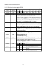
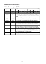
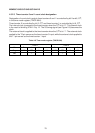
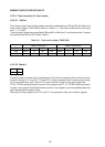
Table 4-8 Timer mode register (TMOD 89H)
Bit 76543210
Flag
GATE C/T M1 M0 GATE C/T M1 M0
Set •
Timer 1 Timer 0
•