


INTERNAL SPECIFICATIONS
57
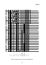
4.2 Internal Data Memory (RAM)
4.2.1 Internal data memory (RAM)
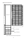
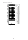
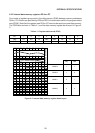
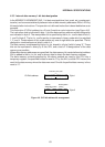
The storage capacity of the MSM80C154S/MSM83C154S data memory is 256 words ¥ 8 bits.
The layout diagram is shown in Figure 4-2.
The data memory can be accessed (R/W) in four different ways - direct register designation,
indirect register designation, data addressing, and bit addressing.
Four banks of registers group (R0 thru R7 ¥ 4) exist within the data memory address range
from 00 to 1FH. Banks are specified by RS0 and RS1 data combinations within the PSW.
The data memory address range from 20 to 2FH is an area where bit addressing is possible.
One bit of data can be manipulated directly by bit manipulation instructions.
The data memory address range from 00 to 7FH is an area where data addressing is possible.
8-bit data manipulations can be handled directly by data address manipulation instructions.
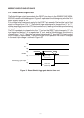
The data memory address range from 80H to 0FFH is an area where data addressing is not
possible. To manipulate data in this data memory area, the contents of register R0 or R1 are
set in 80H thru 0FFH, then an indirect register instruction is used. (Indirect register
instructions can be used to specify the entire data memory from address 00 to 0FFH.)
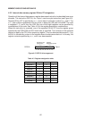
In addition to data storage in the CPU, the data memory is used as the place for saving stack
data. This stack data storage area is addressed by a stack pointer (SP 81H).
Since the stack pointer can be set any desired value by software, the data memory can be
used as stack from any data memory address. Note that 07H data is set automatically in the
stack pointer when the CPU is reset.