


INTERNAL SPECIFICATIONS
121
If the above conditions are not satisfied when the hexadecimal counter is in state 10 during
the multi-purpose data bit interval, the received data is disregarded, the SBUF, RB8, and RI
flags remain unchanged, and the receive circuit is initialized when the hexadecimal counter
is in state 10 during the stop bit interval.
Since the receive circuit is double buffered (input shift register and SBUF), processing of the
previous receive data may be completed within the interval up to the multipurpose data bit
period of the next frame.
4.6.3.4.5 Mode 3 UART error detection
Mode 3 UART error detection is identical to mode 2 UART error detection.
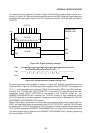
If the following two conditions are satisfied when the hexadecimal counter is in state 10 during
reception of a multi-purpose data bit, it is assumed that new data is received before
processing of the previously received data has been completed. Hence, an overrun error is
generated, and the new data is lost. The SERR flag is set at the first M1·S3 after the
hexadecimal counter has reached state 10 during the stop bit interval. Note that the previous
SBUF (R) data is preserved.
Conditions: (1) RI =“1”
(2) SM2=“0”, or SM2=“1” and sampled multi-purpose data bit=“1”
And if the sampled stop bit is “0” when the hexadecimal counter is in state 10, it is assumed
that correct frame synchronization has not been achieved. Hence, a framing error is detected,
and the SERR flag is set at the first M1·S3 after that.
Serial port reception is not effected by the UART error detector circuit detecting an overrun
or framing error and only the status flag being set.