


MSM80C154S/83C154S/85C154HVS
82
4.5.2.5 Timer/counters 0/1 timer modes
4.5.2.5.1 Outline
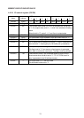
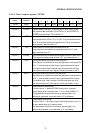
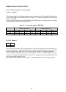
The timer/counter 0 and 1 timer modes are set by combinations of M0 and M1 bit data in the
timer mode register (TMOD 89H) shown in Table 4-11. The timer modes which can be set
are 0, 1, 2, and 3.
Timer/counter 0 modes are specified by M0 and M1 of bits 0 and 1, and timer/counter 1 modes
are specified by M0 and M1 of bits 4 and 5.
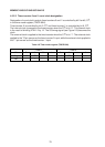
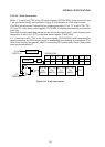
Table 4-11 Timer mode register (TMOD 89H)
TIMER COUNTER 1 TIMER COUNTER 0
Bit
Flag
Set
76543210
GATE C/T M1 M0 GATE C/T M1 M0
•• ••
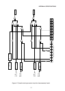
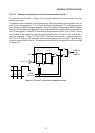
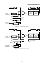
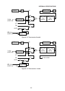
4.5.2.5.2 Mode 0
M1 M0
00
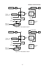
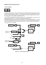
In mode 0, timer/counters 0 and 1 both become 13-bit timer/counters by the circuit connection
shown in Figures 4-11 and 4-12. TL0 and TL1 in timer/counters 0 and 1 serve as the counter
for the five lower bits, and TH0 and TH1 serve as the counter for the eight upper bits.
TF0 of TCON is set by the timer/counter 0 carry signal, and TF1 of TCON is set by the timer/
counter 1 carry signal. Note that the timer/counter 1 carry signal can also be used as the serial
port transmission/reception clock.
Although the three upper bits of TL0 and TL1 are operative, they are invalid as signals.