


INPUT/OUTPUT PORTS
195
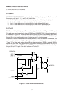
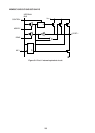
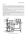
5.3 Port 1
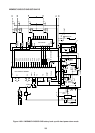
Port 1 is a quasi-bidirectional port capable of handling input and output of 8-bit data in the
circuit configuration outlined in Figure 5-4.
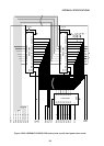
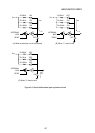
A “quasi-bidirectional port” refers to a port which has internal pull-up resistance when used
as an input port. The internal equivalent circuit is shown in Figure 5-5.
If a quasi-bidirectional port is used exclusively as an output port, the port output driver
becomes a totem-pole type for driving “1” and “0” data. The output impedance during output
of “1” data is approximately 9 kohm, while a sink current is 1.6mA during output of “0” data.
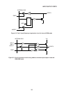
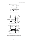
When used as an output port, the “1” data accelerator circuit is activated for a period
equivalent to two XTAL1·2 oscillator clocks only when the output data is shifted from “0” to
“1”. During this data acceleration operation, the “1” output impedance is changed to about 500
ohms, the IOH current is increased, and the output signal leading edge is speeded up. The
accelerator circuit operation time chart is given in Figure 5-6. Once port output data has been
written in port latch it is preserved until output of the next item of data.
If a quasi-bidirectional port is used exclusively as an input port, “1” data is first set in the port
latch in advance. When the input signal applied to the input port is changed from level “1” to
level “0”, the port 10 kohm pull-up resistance is disconnected from the VCC, leaving only the
100 kohm pull-up resistance for reducing external IIL current. And when the input signal is
changed from level “0” to level “1”, the 10 kohm resistance is reconnected, thereby connecting
the 10 and 100 kohm resistances to the VCC supply in parallel. The quasi-bidirectional port
input equivalent circuit is outlined in Figure 5-7.
To change port 1 from a quasi-bidirectional input port to a high impedance input port, “1” is
set in bit 1 (P1HZ) of the I/O control register (IOCON 0F8H). The output driver circuit is thus
disconnected from the port pin and the port becomes a high impedance input port. The signal
levels applied to high impedance input ports are normal “0” and “1” level signals. The pins
cannot be used in open status.
The bit 0 and bit 1 of port 1 have alternate functions apart from serving as port pins. Bit 0 can
function as the external clock input pin for timer/counter 2, and bit 1 can function as the capture
signal input pin for timer/counter 2, or as the auto reload signal input pin, or as the external
timer flag 2 setting pin, depending on the timer/counter 2 operation mode.
When the bit 0 and 1 pins are to be used as timer/counter 2 control pins, “1” must be set in
the port in advance.
And if port output is to be put into floating status during CPU power down mode (PD, HPD),
“1” is to be set in bit 1 (ALF) of the I/O control register (IOCON 0F8H) before CPU power down
mode is activated. Floated port 1 pins may be either open, or undefined within the –0.5 to VCC
+0.5V range.
And when port 1, 2, and 3 quasi-bidirectional ports are used as input ports, the port pull-up
resistance may be set only to 100 kohms. If “1” is set in bit 4 (IZC) of the I/O control register
(IOCON 0F8H), the 10 kohm pull-up resistance for ports 1, 2, and 3 is all disconnected from
VCC, leaving only the 100 kohm resistance. This mode is useful when input data is applied
to the quasi-bidirectional port by external devices having low output driving capacity (high
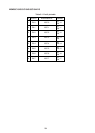
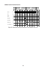
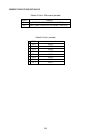
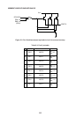
output impedance). The port 1 CPU control pin functions are listed in Table 5-2, and the port
pin list is given in Table 5-3.