


MSM80C154S/83C154S/85C154HVS
132
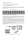
4.7.3 Interrupt priority register (IP)
The function of the interrupt priority register (IP, 0B8H) is to allocate rights to commence
interrupt routines on a priority basis when an interrupt is requested.
Interrupt priority can be programmed by setting the bit corresponding to the interrupt request
in the interrupt priority register (IP) to “1”. If the interrupt conditions have been satisfied for an
interrupt where “1” data has been set, processing of that interrupt is commenced. If another
interrupt (with “0” priority bit) is already being processed, that routine is suspended, and
processing of the higher priority interrupt is commenced. Note that once a priority interrupt
routine has been commenced, processing of the next interrupt cannot start until processing
of the current interrupt has been completed.
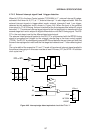
This priority circuit function can be stopped by setting “1” in bit 7 (PCT) of the priority register.
The functions of the priority interrupt control circuit are suspended, and interrupt control is
handled only by the interrupt enable register (IE 0A8H). After this mode has been set, the
interrupt disable instruction (CLR EA) must be placed at the beginning of interrupt routines
to disable the generation of other interrupts.
If another interrupt routine have to be generated during the processing of an interrupt routine,
set the desired interrupt enable bit in the interrupt enable register (IE 0A8H). The desired
interrupt routine is processed when the conditions for that routine are met. Multi-level interrupt
processing can thus be achieved by software control of the interrupt enable register.
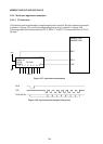
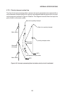
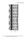
The contents of the interrupt priority register are given in Table 4-20, and a priority interrupt
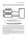
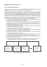
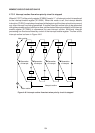
routine flow chart is shown in Figure 4-45. The flow chart for an interrupt routine when the
priority circuit is stopped (PCT=“1”) is shown in Figure 4-46.
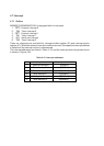
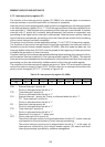
Table 4-20 nterrupt priority register (IP, 0B8H)
76543210
PCT — PT2 PS PT1 PX1 PT0 PX0
Bit
Flag
PX0 : External interrupt 0 priority bit.
Priority is allocated when this bit is “1”.
PT0 : Timer interrupt 0 priority bit.
Priority is allocated when this bit is “1”.
PX1 : External interrupt 1 priority bit. Priority is allocated when this bit is “1”.
PT1 Timer interrupt 1 priority bit.
Priority is allocated when this bit is “1”.
PS : Serial port interrupt priority bit
Priority is allocated when this bit is “1”.
PT2 : Timer interrupt 2 priority bit.
Priority is allocated when this bit is “1”.
— : Reserve bit for output of “1” when read.
PCT : Priority interrupt circuit control bit.
The priority interrupt control circuit is activated when this bit is “0”, and an interrupt
is processed on the priority basis (2 level interrupt processing).
The priority interrupt control circuit is stopped when this bit is “1”. In this case, all
interrupts are controlled by the interrupt enable register (IE) where multi-level
interrupt processing is possible by software management.