


INTERNAL SPECIFICATIONS
63
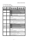
4.3.3 Internal data memory 1-bit data designation
In the MSM80C154S/MSM83C154S, 1-bit data manipulations (test, reset, set, complement,
transfer) can be executed directly between internal data memory addresses 20 thru 2FH by
bit manipulation instructions. The operation of a bit reset instruction is described below as an
example.
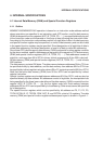
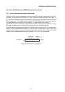
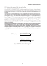
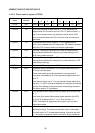
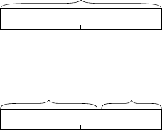
This instruction (CLR bit address) is a 2-byte 2-machine cycle instruction (see Figure 4-6).
The instruction code is indicated in byte 1, and the data memory address and bit designation
are indicated in byte 2. The manipulation bit is specified by the b0, b1, and b2 data in bits 0,
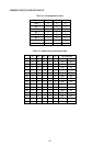
1, and 2 of byte 2. The b0, b1, and b2 portion is expressed in binary code which is weighted
1, 2, and 4. Combinations of this code enable any one of eight bits to be specified. The bit
designation combinations are listed in able 4-4.
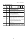
The data memory is addressed by bits b3, b4, b5, b6 and b7 of byte 2 with b7 being “0”. These
bits can be expressed in binary by 0 thru 0FH, and a total of 16 designations of the data
memory are possible.
When data memory addresses are specified, the data memory bit manipulation start address
20H is added to the b3, b4, b5, and b6 binary data to obtain the data memory address.
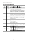
The data memory contents specified by the above method are read by the CPU into a
temporary register, the specified bit data is reset to “0” by the ALU, and the CPU returns the
result to the data memory where the data were read. One bit of specified data memory is thus
reset to “0”.
11000010
76543210
Instruction (OP) code
CLR bit address: Byte 1
b7 b6 b5 b4 b3 b2 b1 b0
76543210
Address
designation portion
Bit designation
portion
Byte 2
Figure 4-6 CLR bit address bit arrangement