


INTERNAL SPECIFICATIONS
187
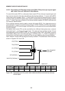
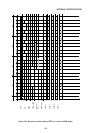
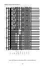
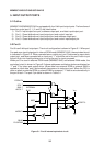
4.10 MSM80C154S/83C154S Battery Backup with Hard Power Down Mode
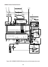
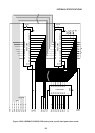
Figures 4-85-1/2 and 2/2 show the examples of the MSM80C154S/83C154S battery backup
circuits with hard power down mode. The hard power down mode serves to retain data stored
in the CPU and external RAM if the AC 100V power failure occurs. Figure 4-85-1/2 shows the
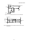
CPU, power failure detector, and external RAM control unit. Figure 4-85-2/2 shows the
external RAM. The power failure detection voltage is set up by VR of the circuit A of Figure
4-85-1/2.
If the AC 100V power failure occurs when the power failure detection voltage is 4.5V, the
circuit works as described below.
When the power failure occurs, the internal power supply voltage VCA goes down from 5V
to 0V. When the VCA goes down less than 4.5V, a power failure detection signal is output from
the A circuit to the B circuit.
If data is being transferred between the CPU and external RAM during the detection of power
failure, information on power failure is stored in RS-F/F of the B circuit, when data transfer
ends. When information on on power failure is stored in RS-F/F, the I/O control signal goes
from “1” level to “0” level, which separates the external RAM and the peripheral circuit
electrically to retain data in the external RAM. At the same time, a hard power down signal
is output, the T1 pin of the CPU goes from “1” level to “0” level, and the CPU enters the hard
power down mode.
If the I/O port is ready to output data during hard power down mode, electric current flows to
the external via a 100KW pull-up resistance of the T1 pin.
The current flow to the external can be prevented by setting “1” into bit 0 (ALF) of IOCON
(0F8H) when setting the hard power down mode. If the hard power down mode is set when
ALF is at “1” level, electric current does not flow from the T1 pin to the external because I/O
becomes a floating state.
When AC 100V power supply is restored and the internal VCA goes from 0V to 5V, the hard
power down mode is cancelled.
When VCA exceeds 4.5V, the A circuit stops outputting a power failure signal for the B circuit.
When a power failure signal is not output, the power failure memory RS-F/F of the B circuit
is reset after a time constant of the internal 200W and 10mF, and the external RAM I/O control
signal and hard power down signal turn from “0” level to “1” level.
When RS-F/F is reset, a CPU reset signal is output and the CPU’s power down mode is
cancelled. The CPU starts the operation of XTAL1, 2 and executes a command starting from
address 0.