


INTERNAL SPECIFICATIONS
151
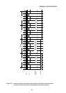
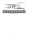
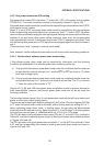
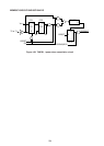
4.8.3 Soft power down mode (PD) setting
Soft power down mode (PD) is set when “1” is set in bit 1 (PD) of the power control register
(PCON 87H). The circuit connection involved in this setting is shown in Figure 4-56.
Soft power down mode cancellation conditions can be set through manipulation of bit 5 (RPD)
of the power control register.
When “0” is set in RPD, soft power down mode cannot be cancelled by the interrupt signal
if the corresponding interrupt enable bit has not been set. And if “1” is set in RPD, the power
down mode is cancelled by setting the interrupt flag and the program is executed from the next
address of the soft power down mode setting instruction, even when the corresponding
interrupt enable bit is not set. In soft power down mode, XTAL1·2 operations are halted. Then
with all internal data preserved, all CPU operations are stopped apart from timer/counters 0
and 1.
(Timer/counters 0 and 1 operate in external clock mode.)
Note, however, that the soft power down mode can not be set under the following conditions.
4.8.3.1 Caution about software power down mode setting
If the software power down mode can be cancelled by interruption and the following
conditions are established, the software power down mode cannot be set.
(1) If trying to set the software power down mode under the conditions that the mode can
be cancelled by external interrupt 0 or 1 and the INT0 or INT1 pin is set to "0" (either
level input or edge input).
(2) If trying to set the software power down mode under the conditions that the mode can
be cancelled by timer 0 or 1 (external clock mode is set) and the T0 or T1 pin is set to
"1" when the value of the counter is "FF".
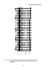
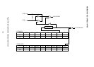
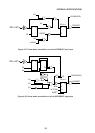
Figures 4-57, 4-58, and 4-59 show power down cancellation circuits by external interrupt or
timer interrupt.Note, however, that the soft power down mode can not be set under the
following conditions.
The pin output status of ports 0 thru 3 in soft power down mode can be left in port data output
status, or set to port output floating status.
The ports are set to data output status by setting bit 0 (ALF) of the I/O control register (IOCON)
to “0” when soft power down mode is activated, and to floating status by setting ALF to “1”
before activating power down mode. In floating status, the port pins are disconnected
electrically from the external circuitry. Apart from pins 2,3, 4, and 5 of port 3, all floating status
input port pins may be open, or undefined within the –0.5 to VCC+0.5V range.
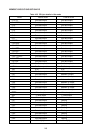
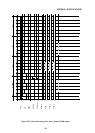
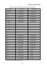
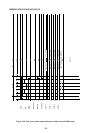
The CPU pin status during soft power down mode (PD) with “0” on the ALF bit is /outlined in
Table 424, and the corresponding time charts for starting soft power down mode are shown
in Figures 4-60 and 4-61.
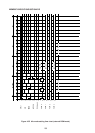
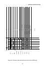
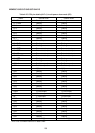
The CPU pin status during soft power down mode with “1” on the ALF bit is outlined in Table
4-25, and the corresponding time charts for starting soft power down mode are shown in
Figures 4-62 and 4-63.