


INTERNAL SPECIFICATIONS
95
XTAL 1 ÷
12
S3
DETECTOR
T2
[PORT 1.0]
Q0------Q7
TL2
8 BIT
C
RCAP2L
Q0------Q7
TH2
8 BIT
C
RCAP2H
DETECTOR
T2EX
[PORT 1.1]
TR2
EXEN2
DETECTOR
DETECTOR
TF2
EXF2
TIMER 2
INTERRUPT
RCLK=0
TCLK=0
CP/
RL2
=1
C/
T2
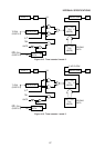
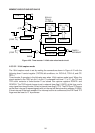
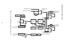
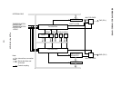
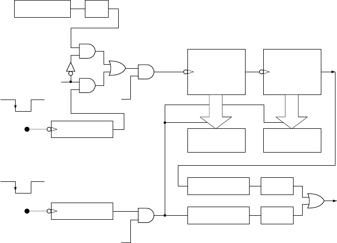
Figure 4-21 Timer/counter 2 16-bit capture mode circuit
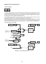
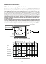
4.5.3.3.3 16-bit baud rate generator mode
The 16-bit baud rate generator mode is set by making the connections shown in Figure 4-22
with the following timer 2 control register (T2CON) bit conditions, viz.
RCLK+TCLK=1.
Timer/counter 2 commences to operate in the following way when 16-bit baud rate generator
mode is set.
Timer/counter 2 is put into 16-bit auto reload mode. When timer/counter 2 generates a carry
signal, the reload data in the RCAP2L and RCAP2H registers is preset in the timer/counter
2 TL2 and TH2 and the timer/counter commences to count from that preset value. The carry
signal is passed to a serial port.
The timer/counter 2 carry signal activates the serial port receive circuit when RCLK 1, and
activates the transmit circuit when TCLK=1. Note, however, that the serial port can use these
clocks only when the serial port is in mode 1 and 3.
When in this mode, the timer/counter 2 carry signal is not set in internal timer flag 2 (TF2).
But since the change in level (from “1” to “0”) of the signal applied to the T2EX pin (bit 1 of
port 1) is set in external timer flag 2, the T2EX pin can be used for ordinary external interrupt
input pin. If an interrupt routine is commenced, the EXF2 flag must be reset to “0” by software.
Since timer/counter 2 is operated at 1/2 of the XTAL1·2 clock if the internal clock is used in
this mode, only undefined data will be read from the timer/counter 2 TL2 and TH2 by software.
Correct data, however, is read from the RCAP2L and RCAP2H registers.