


MSM80C154S/83C154S/85C154HVS
128
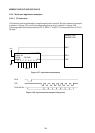
4.6.4.2 Multi-processor systems
Multi-processor systems can be formed with MSM80C154S/MSM83C154S by using the
serial port in mode 2 or mode 3 for inter-processor communications.
If reception data bit 9 (multi-purpose data bit) is “1” when SM2 is set in mode 2 or 3, reception
data is received and an interrupt is generated. If the data bit is “0”, however, the reception data
is disregarded and no interrupt is generated. This function is used in forming a multi-processor
system when more than one MSM80C154S/MSM83C154S device is coupled by serial bus.
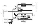
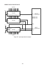
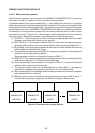
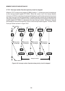
An example of a multi-processor system with one master processor and a number of slave
processors is shown in Figure 4-43. In this example, data is transmitted only from master to
slave processors. Operation proceeds in accordance with the following protocol.
(1) Set SM2=“1”. All slave processors wait in standby for address data from the master
processor specifying which slave is to be selected.
(2) With TB8 set to “1” to distinguish address data from other data, the master processor
generates address data which ensures that data bit 9 (the multi-purpose data bit) is “1”.
(3) At this stage, all slave processors generate interrupts and check whether the received
address data has specified itself or not.
(4) The specified slave processor sets SM2 “0” to prepare for reception of the subsequent
data to be sent by the master processor.
Slave processors which are not specified remain at SM2=“1”
(5) With TB8=“0”, the master processor next sends data which ensures that data bit 9 (the
multi-purpose data bit) is “0” following the address data.
(6) Since the specified slave processor is changed to SM2=“0”, all data following the
address data is received and processed.
(7) The slave processors which are not specified (that is, where SM2=“1”) disregard all
data after the address data and wait in standby for the next address data.
(8) After transmitting all of the intended data the master processor transmits a final special
code (predetermined in advance).
(9) When this special code is received by the specified slave processor, SM2 is set to “1”
and that slave processor is again put into standby waiting for address data.
MSM83C154S
(MASTER)
TXD RXD
MSM83C154S
(SLAVE)
TXD RXD
MSM83C154S
(SLAVE)
TXD RXD
MSM83C154S
(SLAVE)
TXD RXD
Figure 4-43 Multi-processor system example