


MSM80C154S/83C154S/85C154HVS
134
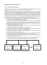
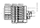
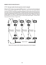
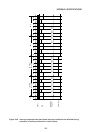
4.7.3.2 Interrupt routine flow when priority circuit is stopped
When bit 7 (PCT) of the priority register (IP 0B8H) is set to “1”, all interrupt control is transferred
to the interrupt enable register (IE 0A8H). When this mode is set, the interrupt disable
instruction (CLR EA) must always be placed at the beginning of the interrupt routine to prevent
any other interrupt from being generated. If another interrupt routine have to be generated
during the processing of an interrupt routine, set the desired interrupt enable bit in the interrupt
enable register (IE 0A8H) to commence the new interrupt routine. Multi-level interrupt
processing can thus be achieved by control of the interrupt enable register. The flow of this
interrupt routine is shown in Figure 4-46.
Generation
of interrput
M
EA EA
CLREA
Generation
of interrput
EA
CLREA
Generation
of interrput
EA
CLREA
Generation
of interrput
CLREA
EA
RETI RETI RETI RETI
M
Interrput routine
Main routine
Main routine
Figure 4-46 lnterrupt routine flow chart when priority circuit is stopped