


MSM80C154S/83C154S/85C154HVS
62
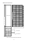
4.3.2 Internal data memory register R0 thru R7 designation
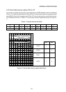
Operation of the internal data memory register decrement instruction is described here as an
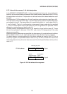
example. This instruction (DEC Rr) is a 1-byte 1-machine cycle instruction (see Figure 4-5).
Register R0 thru R7 is specified by r0, r1, and r2 data of instruction code bit 0, 1, and 2. The
r0, r1, and r2 data is represented in binary code, r0 being the LSB, and r2 the MSB. The code
is weighted 1, 2, and 4 from the LSB. Any one of the eight registers can be specified by
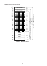
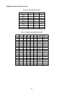
combinations of this code. See Table 4-3 for the register designation combinations.
When this instruction is executed, one of the registers R0 thru R7 from the register group
specified by the PSW RS0 and RS1 bank data is specified. The contents of the specified
register is read by the CPU into a temporary register. Then a subsequent decrement (–1) by
the ALU is followed by a return to the register where the data were read out. In this way, the
register contents specified by r0, r1, and r2 are decremented.
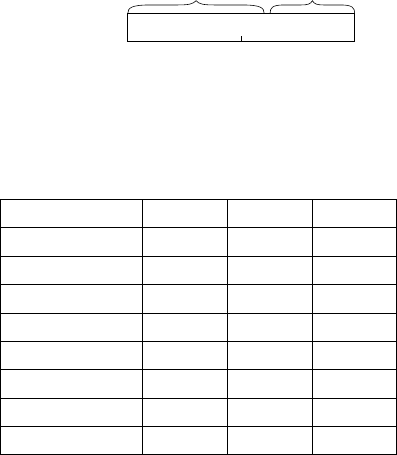
00011r2 r1 r0
76543210
Instruction (OP)
code portion
Register
designation portion
DEC Rr: Byte 1
Figure 4-5 DEC Rr bit arrangement
Table 4-3 Register designation table
Register name
Register 0
Register 1
Register 2
Register 3
Register 4
Register 5
Register 6
Register 7
r2 r1 r0
000
001
010
011
100
101
110
111