


MSM80C154S/83C154S/85C154HVS
76
4.5 Timer/Counters 0, 1 and 2
4.5.1 Outline
Timer/counters 0, 1 and 2 are all equipped with 16-bit binary up-counting and Read/Write
functions, and can be operated independently.
All control of timer/counters 0 and 1 is handled by the timer control register (TCON 88H) and
the timer mode register (TMOD 89H). And both timer/counters can be set independently to
modes 0 thru 3 for a diversity of applications.
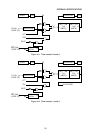
Timer/counters 0 and 1 can be operated by an external clock applied to the T0 and T1 pins
(if external clock mode has been set) during soft power down mode (PD) and hard power
down mode (HPD) where XTAL1·2 are stopped. Therefore, CPU power down mode can be
cancelled by generating a timer/counter carry signal.
Timer/counter 2 can be fully controlled by timer 2 control register (T2CON 0C8H). There are
three operational modes for a wide range of applications. Note that counting is stopped when
XTAL1·2 are stopped.
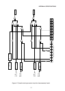
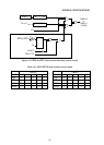
4.5.2 Timer/counters 0 and 1
4.5.2.1 Outline
Timer/counters 0 and 1 are both equipped with a 16-bit binary counting function which can
be operated independently.
All control of timer/counters 0 and 1 is handled by the timer control register (TCON) and the
timer mode register (TMOD). And both timer/counters can be set independently to modes 0
thru 3 for a diversity of applications. The overall control circuit for timer/counters 0 and 1 is
outlined in Figure 4-7 (excluding timer mode 3).
4.5.2.2 Timer/counter 0 and 1 counting control
Counting start and stop in timer/counters 0 and 1 is controlled by bit 4, TR0, and bit 6, TR1,
in the timer control register (TCON 88H) as indicated in Table 4-7.
TR0 controls timer/counter 0, and TR1 controls timer/counter 1. Timer/counter operation is
stopped when the bit data is “0”, and enabled when “1”.
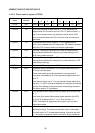
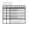
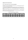
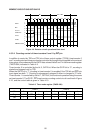
Table 4-7 Timer control register (TCON 88H)
Bit 76543210
Flag TF1 TR1 TF0 TR0 IE1 IT1 IE0 IT0
Set • •
Timer 1 Timer 0