


MSM80C154S/83C154S/85C154HVS
80
S1 S2 S3 S4 S5 S6
M1
S1 S2 S3 S4 S5 S6
M1 or M2
S1
XTAL1
1
0
ALE
1
0
T0 or T1
COUNT IN
1
0
F/F2Q
1
0
TIMER COUNT
1
0
F/F1Q
1
0
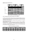
S2S6
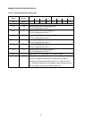
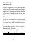
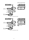
Figure 4-9 Detector circuit operational time chart
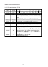
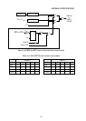
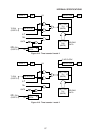
4.5.2.4 Counting control of timer/counters 0 and 1 by INT pin
In addition to control by TR0 and TR1 bits of timer control register (TCON), timer/counter 0
and 1 counting start and stop can also be controlled by the signal level applied to the external
interrupt pin in accordance with the GATE data values of bits 3 and 7 in the timer mode register
(TMOD 89H) indicated in Table 4-9.
Timer/counter 0 is controlled by the bit 3, GATE bit. When the GATE bit is “0”, counting is
started and stopped only by TR0.
When the GATE bit is “1”, counting in timer/counter 0 is enabled if the TR0 bit and INT0 pin
input signal are both “1”. Counting is subsequently stopped if either is changed to “0” level.
Timer/counter 1 is controlled by the bit 7, GATE bit, the functional operation being the same
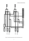
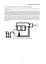
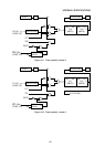
as timer/counter 0. The GATE - INT timer/counter counting control circuit is outlined in Figure
4-10, and the control table is given in Table 4-10.
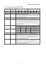
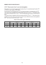
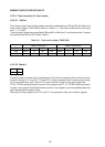
Table 4-9 Timer mode register (TMOD 89H)
Timer 1 Timer 0
Bit
Flag
Set
76543210
GATE C/T M1 M0 GATE C/T M1 M0
••