


INTERNAL SPECIFICATIONS
67
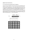
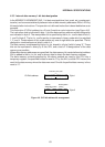
4.4.2 Special function registers
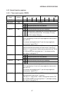
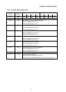
4.4.2.1 Timer mode register (TMOD)
TMOD 89H GATE C/T M1 M0 GATE C/T M1 M0
Name Address
MSB LSB
76543210
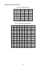
Bit location Flag Function
TMOD.0
TMOD.1
TMOD.2
TMOD.3
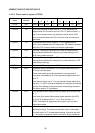
TMOD.4
TMOD.5
TMOD.6
TMOD.7
M0
M1
C/T
GATE
M0
M1
C/T
GATE
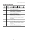
Timer/counter 0 mode setting
8-bit timer/counter with 5-bit prescalar
16-bit timer/counter
8-bit timer/counter with 8-bit auto reloading
Timer/counter 0 separated into TL0 (8-bit) timer/counter
and TH0 (8-bit) timer/counter. TF0 is set by TL0 carry,
and TF1 is set by TH0 carry.
Timer/counter 0 count clock designation control bit.
XTAL1·2 divided by 12 clock is the input applied to timer/counter 0
when C/T="0".
The external clock applied to the T0 pin is the input applied to
timer/counter 0 when C/T="1".
When this bit is "0", the TR0 bit of TCON (timer control register) is
used to control the start and stop of timer/counter 0 counting. If
this bit is "1", timer/counter 0 starts counting when both the TR0 bit
of TCON and INT0 pin input signal are "1", and stops counting
when either is changed to "0".
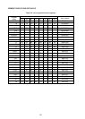
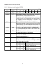
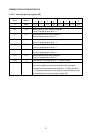
Timer/counter 1 mode setting
8-bit timer/counter with 5-bit prescalar
16-bit timer/counter
8-bit timer/counter with 8-bit auto reloading
Timer/counter 1 operation stopped
Timer/counter 1 count clock designation control bit.
XTAL1·2 divided by 12 clock is the input applied to timer/counter 1
when C/T="0".
The external clock applied to the T1 pin is the input applied to
timer/counter 1 when C/T="1".
When this bit is "0", the TR1 bit of TCON is used to control the
start and stop of timer/counter 1 counting.
If this bit is "1", timer/counter 1 starts counting when both the TR1
bit of TCON and INT1 pin input signal are "1", and stops counting
when either is changed to "0".
M1
0
0
1
1
M0
0
1
0
1
M1
0
0
1
1
M0
0
1
0
1