


INTERNAL SPECIFICATIONS
161
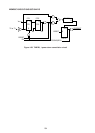
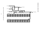
4.8.4 Hard power down mode (HPD) setting
To set hard power down mode (HPD), “1” is set in bit 6 (HPD) of the power control register
(PCON 87H) in advance to attain the circuit connections shown in Figure 4-61. Hard power
down mode is set when the level of the power failure detect signal applied to the HPDI pin
(bit 5 of port 3) is changed from level “1” to level “0”. XTAL1·2 operations are stopped in this
mode. And while all internal data is retained, the CPU operations also are stopped apart from
timer/counter 0 and 1. (Timer/counters 0 and 1 operate in external clock mode.)
The pin output status of ports 0 thru 3 in hard power down mode can be left in port data output
status, or set to port output floating status.
The ports are set to data output status by setting bit 0 (ALF) of the I/O control register (IOCON
0F8H) to “0” when hard power down mode is activated, and to floating status by setting ALF
to “1” before activating power down mode. In floating status, the port pins are disconnected
electrically from the external circuitry.
Apart from pins 2, 3, 4, and 5 of port 3, all floating status input port pins may be open, or
undefined within the –0.5 to VCC+0.5 V range.
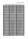
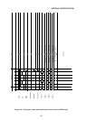
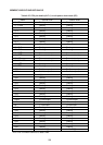
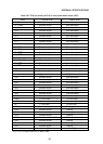
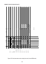
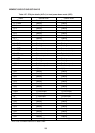
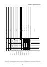
The CPU pin status during hard power down mode (HPD) with “0” on the ALF bit is outlined
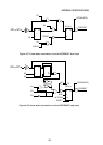
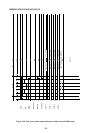
in Table 4-26, and the corresponding time charts for starting hard power down mode are
shown in Figures 4-65 and 4-66.
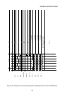
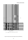
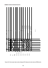
And the CPU pin status during hard power down mode (HPD) with “1” on the ALF bit is outlined
in Table 4-27, and the corresponding time charts for starting hard power down mode are
shown in Figures 4-67 and 4-68.