


INTERNAL SPECIFICATIONS
131
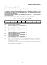
4.7.2 Interrupt enable register (IE)
The function of the interrupt enable register (IE, 0A8H) is to enable or disable interrupt
processes when an interrupt is requested.
To execute the intended interrupt routine, the interrupt is first enabled by setting “1” in the
corresponding interrupt bit in the interrupt enable register, and the routine then is executed
when the interrupt is requested.
Requested interrupts are disabled if the corresponding interrupt bit is “0”, and no interrupt
routines are executed.
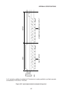
The contents of the interrupt enable register (IE) are shown in Table 4-19.
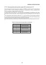
Table 4-19 lnterrupt enable register (IE, 0A8H)
76543210
EA — ET2 ES ET1 EX1 ET0 EX0
Bit
Flag
EX0 : External interrupt 0 control bit
Interrupt enabled when “1”, disabled when “0”.
ET0 : Timer interrupt 0 control bit
Interrupt enabled when “1”, disabled when “0”.
EX1 : External interrupt 1 control bit
Interrupt enabled when “1”, disabled when “0”.
ET1 : Timer interrupt 1 control bit
Interrupt enabled when “1”, disabled when “0”.
ES : Serial port interrupt control bit
Interrupt enabled when “1”, disabled when “0”.
ET2 : Timer interrupt 2 control bit
Interrupt enabled when “1”, disabled when “0”.
— : Reserve bit for output of “1” when read.
EA : Interrupt control bit for all six interrupts (EX0, ET0, EX1, ET1, ES, and ET2) When
EA is “1”, an interrupt routine is commenced if interrupt conditions are met for any
one of the six interrupts.
When EA is “0”, no interrupt routine is commenced even if interrupt conditions are
met for one of the six interrupts.