


MSM80C154S/83C154S/85C154HVS
192
5. INPUT/OUTPUT PORTS
5.1 Outline
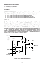
MSM80C154S/MSM83C154S is equipped with four 8-bit input/output ports. The functions of
these four ports (port 0, 1, 2, and 3) are listed below.
1) Port 0: Input/output bus port, address output port, and data input/output port.
2) Port 1: Quasi-bidirectional input/output port and control input pin.
3) Port 2: Quasi-bidirectional input/output port and address output port.
4) Port 3: Quasi-bidirectional input/output port and control input/output pin.
5.2 Port 0
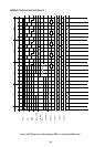
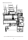
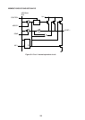
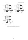
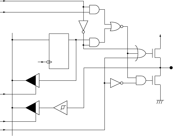
Port 0 is an 8-bit input/output port. The circuit configuration is shown in Figure 5-1. When port
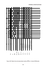
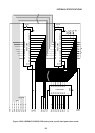
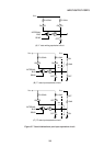
0 is used as an input/output port in internal ROM mode (MSM83C154S), the equivalent circuit
is indicated in Figure 5-2. When operated as an output port, port 0 becomes an open drain
output port, and when operated as an input port, “1” should be set in the port 0 latch to put
the port 0 pin into floating status prior to using the port for input purposes.
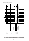
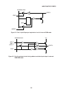
When port 0 is used in external ROM mode (MSM80C154S) and external RAM mode, the
equivalent circuit is shown in Figure 5-3 where addresses and data outputs are obtained as
“1” and “0” by totem pole output driver. When data from external ROM or external RAM is
applied as input data, port 0 automatically becomes a tri-state input port. When the CPU is
reset or when an external ROM or external RAM is accessed, “1” data is set automatically in
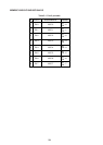
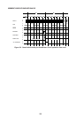
the port 0 latch. The port 0 pin table is shown in Table 5-1.
QD
PD/DATA
PC0~7
RA0~7
ACC0~7
MODIFY
READ
FLOATING
INTERNAL
BUS
WPO
N
P
VCC
PORT 0
Figure 5-1 Port 0 internal equivalent circuit