


SYSTEM CONFIGURATION
21
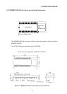
2.6 Timing and Control
2.6.1 Outline of MSM80C154S/MSM83C154S timing
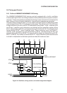
The MSM80C154S/MSM83C154S devices are both equipped with a built-in oscillation
inverter (see Figure 2-8) for use in the generation of clock pulses by external crystal or ceramic
resonator. These clock pulses are passed to the timing counter and control circuits where the
basic timing and control signals required for internal control purposes are generated.
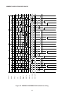
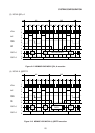
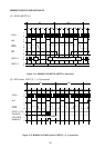
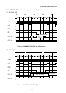
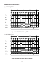
The basic timing consists of state 1 (S1) thru state 6 (S6) (see Figure 2-9) where each state
cycle is based on two XTAL1·2 fundamental clock pulses. The interval from S1 thru S6 forms
a single machine cycle with a total of 12 fundamental clock pulses. 1-byte 1-machine cycle
and 2-byte 1-machine cycle instructions are fetched into the instruction register during
M1·S1, decoded during M1·S2, and executed during M1·S3 thru M1·S6. The second byte is
fetched during M1·S4. 1-byte 2-machine cycle, 2-byte 2-machine cycle, and 3-byte 2-
machine cycle instructions are also fetched during M1·S1, decoded during M1·S2, and
executed during M1·S3 thru M2·S6. The second and third bytes are fetched during M1·S4,
M2·S1, or M2·S4. The number of clocks used is 24. 1-byte 4-machine cycle instructions are
involved in multiplication and division operations where 48 clocks are used.
1/2
DQ DQ DQ DQ DQ
S1 S2 S3 S4 S5 S6
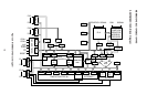
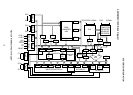
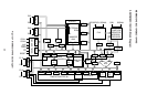
S I/O & TIMER CONTROL
S I/O
TIMER & INTERRUPT
1/2
XTAL2
XTAL1
RESET
INT
CPU CONTROL
POWER DOWN
IDLE
CPU
PLA
PLA OUT
DQ
Figure 2-8 Oscillator, timing counter, and control stage block diagram