


MSM80C154S/83C154S/85C154HVS
116
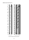
When this “1” to “0” RXD change is detected, the hexadecimal counter which had been
stopped in reset status commences to count up. When the hexadecimal counter is in state
7, 8, and 9, the start bit is sampled, and is accepted as valid if at least two of the three sampled
values are “0”, thereby enabling data reception to continue. If two or three of the sampled
values are “1”, the start bit becomes invalid, and the receive circuit is initialized when the
hexadecimal counter reaches state 10.
The receive data is sampled when the hexadecimal counter is in state 7, 8, and 9, and the
more common value of the three sampled values is read sequentially as data into the input
shift register.
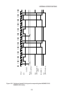
If the hexadecimal counter is in state 10 during the period of the next bit (that is, the multi-
purpose data bit) after the eight bits of data have been received, and if the conditions stated
below are satisfied, the input shift register data (the LSB being read first) is loaded into SBUF,
and the sampled multi-purpose data bit is read into RB8. And when the hexadecimal counter
is in state 10 during the period of the next after that (that is, the stop bit) the receive circuit
is initialized.
The RI flag is set at the first M1·S3 after that.
Conditions: (1) R1=“0”
(2) SM2=“0”, or SM2=“1” and sampled multi-purpose data bit=“1”
If the above conditions are not satisfied when the hexadecimal counter is in state 10 during
the multi-purpose data bit interval, the received data is disregarded, the SBUF, RB8, and RI
flags remain unchanged, and the receive circuit is initialized when the hexadecimal counter
is in state 10 during the stop bit interval.
Since the receive circuit is double buffered (input shift register and SBUF), processing of the
previous receive data may by completed within the interval up to the multipurpose data bit
period of the next frame.
4.6.3.3.5 Mode 2 UART error detection
If the following two conditions are satisfied when the hexadecimal counter is in state 1 0 during
reception of a multi-purpose data bit, it is assumed that new data is received before
processing of the previously received data has been completed. Hence, an overrun error is
generated, and the new data is lost. The SERR flag is set at the first M1·S3 after the
hexadecimal counter has reached state 10 during the stop bit interval. Note that the previous
SBUF (R) data is preserved.
Conditions: (1) R1 =“1”
(2) SM2=“0”, or SM2=“1” and sampled multi-purpose data bit=“1”
And if the sampled stop bit is “0” when the hexadecimal counter is in state 10, it is assumed
that correct frame synchronization has not been achieved. Hence, a framing error is detected,
and the SERR flag is set at the first M1·S3 after that. Serial port reception is not effected by
the UART error detector circuit detecting an overrun or framing error and only the status flag
being set.