


INPUT/OUTPUT PORTS
207
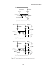
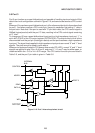
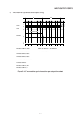
5.7 High Impedance Input Port Setting of Each Ouasi-bidirectional Port 1, 2,
and 3
Each of the quasi-bidirectional input ports 1, 2, and 3 can be set as high impedance input
ports.
This high impedance condition is achieved by setting “1” in bits 1 (P1HZ), 2 (P2HZ), and 3
(P3HZ) of the I/O control register (IOCON 0F8H) shown in Figure 5-11. Port 1 is set by P1HZ,
port 2 by P2HZ, and port 3 by P3HZ. When the each bit is set to “1”, the port output driver is
disconnected from the port pins, and the quasibidirectional input ports become high
impedance input ports.
After being changed to high impedance input ports, the port latch data modify instructions and
the input instructions for external input signals can still be used.
Normal “0” and “1” level signals must be applied to high impedance input ports. The pins
cannot be used in open status.
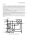
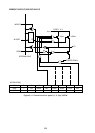
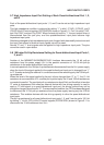
5.8 100 kohm Pull-Up Resistance Setting for Quasi-bidirectional Input Ports 1,
2, and 3
Another of the MSM80C154S/MSM83C154S functions disconnects the 10 kW pull-up
resistance from the power supply VCC in the parallel connection of 10/100 kW pull-up
resistances to the quasi-bidirectional input ports.
In normal operations, the 10 kW pull-up resistance is disconnected from the VCC power supply
when the level of the signal applied to the quasi-bidirectional input port is changed from “1”
to “0”, thereby reducing the external IIL current because of the remaining only the 100 kW pull-
up resistance.
When the level of the signal applied to the port is then changed from “0” to “1”, the 10 kW
resistance is reconnected to VCC, and the port is pulled up by the 10 and 100 kW resistances
connected in parallel. The resultant pull-up resistance is about 9 kW and the effect of random
“0” noise is suppressed. But where an external device with low driving capacity is used to
apply a “0” level signal to a quasi-bidirectional input port, the driving current may not be
enough to change the port level to “0”. To overcome this problem, the CPU has been designed
to disconnect the 10 kW pull-up resistance from the power supply leaving only the 100 kW
resistance. This enables devices with low driving capacity to drive the quasi-bidirectional
input ports.
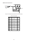
The pull-up resistance for all quasi-bidirectional input ports 1, 2, and 3 can be set to 100 kW
by setting “1” in bit 4 (IZC) of the I/O control register (IOCON 0F8H) shown in Figure 5-11 to
disconnect the 10 kW resistance from VCC.