8842A
Instruction Manual
3-32
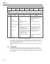
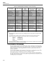
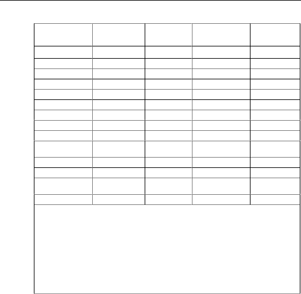
Table 3-3. Immediate-Mode Commands for Various Controllers
FUNTION
PERFORMED
FLUKE-BASIC on
1720A or 1722A
HP-HPL on
HP9825
Calculator
HP-BASIC on
HP9816-PC and HP-
85 Calculator
TEK-BASIC on
4051 Graphics
System
INITIALIZE Port INIT PORT 0 cli 7 CLEAR 7 INIT
CLEAR Instrument CLEAR @4 cir 704 CLEAR 704 PRINT @4: “*”
REMOTE Commands REMOTE @4 rem 704 REMOTE 704 WBYTE @36, 17:
LOCAL Control LOCAL @4 Icl 704 LOCAL 704 WBYTE @36, 1:
EXTERNAL TRIGGER PRINT @4,”T1” wrt 704,”T1” OUTPUT 704;”T1” PRINT @4:”T1”
TRIGGER Instrument TRIG @4 trg 704 TRIGGER 704 PRINT @4:”?”
GET Output Data INPUT @4,A red 704, A ENTER 704;A (Note 2) INPUT @4:A
PRINT Data to Screen PRINT A prt A PRINT A (Note 2) PRINT A
CONFIGURE for VAC PRINT @4,”F2” wrt 704,”F2” OUTPUT 704;”F2” PRINT @4:”F2”
CONFIGURE for
200Vac
PRINT @4,”R4” wrt 704;”R4” OUTPUT 704;”R4” PRINT @4:”R4”
TRIGGER Continuously PRINT @4,”TO” wrt 704,”TO” OUTPUT 704; “TO” PRINT @4:”TO”
SUFFIXES Enable PRINT @4,”Y1” wrt 704,”Y1” OUTPUT 704;”Y1” PRINT @4:”Y1”
GET Data & Suffix INPUT @4, A,A$ Red 704,A,A$
(Note 1)
ENTER 704;A,A$ (Note
2)
INPUT %4:A,A$
PRINT Data & Suffix PRINT A,A$ Prt A$,A PRINT A,A$ (Note 2) PRINT A,A$
Notes:
1. Before using A$ on the 9825 is necessary to enter ”dimA$[6]” to allocate a string variable. This statement allows
six characters.
2. In the HP9816 system, variables cannot be created from the keyboard; they must be created by running a
program. (See error 910 for that system.) To get around this, type in a very short program as follows:
SCRATCH (Hit “EXEC” key)
10 A = 0 (Hit “ENTER” key)
20 A$ = ‘’’’ (Hit “ENTER” key)
30 END (Hit “ENTER” key)
(Hit “RUN” Key)
This program creates the variables ‘A’ and ‘A$’ so that they may be accessed in immediate mode and changed at
will. This program is not necessary for the HP-85 Calculator.
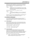
3-60. EXAMPLE PROGRAMS
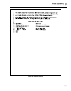
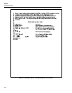
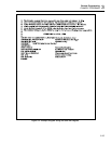
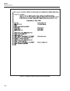
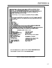
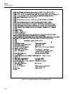
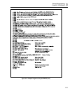
Several example programs for the 8842A using various controllers are presented in the
remaining figures in this section. In all of these examples, the 8842A is set to IEEE-488
address 4 (rear panel switch setting 000100). Of course, any other address (00 to 30)
could be substituted.
In each of these examples, the instrument is cleared prior to configuration set-ups. This
ensures that the 8842A configuration has been completely defined.
To run these programs, it is not necessary to type in all the comments (which appear to
the right of the exclamation marks). Also, spaces are placed between commands for ease
of reading; they are not required.


