


Maintenance
TROUBLESHOOTING
6
6-67
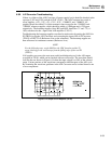
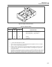
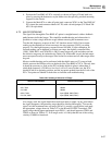
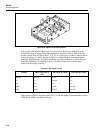
4. Position the True RMS AC PCA vertically as shown in Figure 6-20 and latch it in
place by pressing the bottom two nylon latches into the specially provided mounting
supports on the chassis.
5. Connect the Main PCA ac take-off point (stud connector W301) to the True RMS AC
PCA input (the stud connector labeled AC IN) with a 6-inch jumper (E-Z-Hook 204-
6W-S or equivalent).
6-73. MAJOR PROBLEMS
The signal flow through the True RMS AC option is straightforward, with no feedback
paths between individual stages. This simplifies troubleshooting and often makes it
possible to isolate a single defective stage without removing the instrument cover.
Test the mid-frequency response of the VAC function around 1 kHz. If an accurate
reading can be obtained on at least one range, the rms converter (U802) is working
properly. Test the high-frequency response around 100 kHz. If, after calibration, an
accurate reading can be obtained on at least one range, the digitally controlled filter
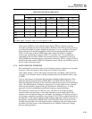
(U801, U808, R832, and C826-829) is OK. If some ranges are good and others are bad,
the defective stage may be isolated using Table 6-26. If this table is used, the bad ranges
must correspond exactly to the ranges listed in the first column and all other ranges must
be good.
Most ac troubleshooting can be performed with the shields removed. To remove both
shields, unscrew the Phillips screw on the back of the True RMS AC PCA. The only time
it should be necessary to work on the PCA with the shields in place is when there is
subtle high-frequency (>20 kHz) or low-level (<10 mV) error. In that case, the PCA
should be left in its operating position, and the test points probed from the foil side of the
PCA. Test points are labeled on both sides to facilitate such troubleshooting.
Table 6-26. Isolating a Defective AC Stage
DEFECTIVE RANGES DEFECTIVE STAGE
200 mV, 2000 mA U806B
20V, 700V U806A
2V, 200V U806A
200V, 700V Input (Q806, K802, Z801)
2V, 20V, 200V Input (Q806, K802, Z801)
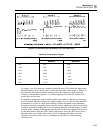
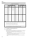
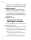
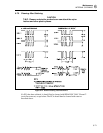
If no ranges work, the signal should be traced from input to output. At any point where
the signal disappears, the preceding stage should be searched thoroughly. To trace the
signal, lock the instrument into one range (200 mV is usually a good choice) and apply
the appropriate voltage shown in Table 6-27 to the HI and LO INPUT terminals. The
input voltage should appear unchanged at pin Z801-1, and should appear at TP801 and
TP802 as shown in Table 6-27. If no ranges work, it is likely that the rest of the scaling
circuitry (U806B) is functional.