


ix
List of Figures
Figure Title Page
1-1. External Dimensions.............................................................................................. 1-11
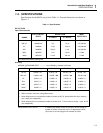
2-1. Line Voltage Selection Settings............................................................................. 2-2
2-2. Adjusting the Handle ............................................................................................. 2-3
2-3. Rack-Mount Kits.................................................................................................... 2-3
2-4. Installing the Single Rack Mount Kit .................................................................... 2-4
2-5. Front Panel Features .............................................................................................. 2-5
2-6. Rear Panel Features ............................................................................................... 2-7
2-7. Typical Error Messages ......................................................................................... 2-8
2-8. Overrange Indication ............................................................................................. 2-12
2-9. Measuring Voltage and Resistance........................................................................ 2-15
2-10. Measuring Current................................................................................................. 2-15
3-1. IEEE-488 Address Selection.................................................................................. 3-4
3-2. Remote Operation Block Diagram......................................................................... 3-5
3-3. Typical Command String....................................................................................... 3-6
3-4. Commands Which Correspond to the Front Panel................................................. 3-7
3-5. Device-Dependent Command Set.......................................................................... 3-8
3-6. Output Data Format ............................................................................................... 3-10
3-6. Trigger Selection Logic Diagram .......................................................................... 3-18
3-7. Interpretation of Messages..................................................................................... 3-22
3-9. Example Program................................................................................................... 3-33
3-10. Example Program: Taking Readings with Local Control...................................... 3-34
3-11. Example Program: Using the Serial Poll Register................................................. 3-35
3-12. Example Program: Record Errors During Selftest................................................. 3-36
3-13. Example Programs: Using the IBM PC................................................................. 3-37
4-1. Circuit Loading Error Calculation ......................................................................... 4-2
4-2. Measuring Input Bias Current Error ...................................................................... 4-3
4-3. Wire Ohms Measurement...................................................................................... 4-4
4-4. Wire Ohms Measurement...................................................................................... 4-6
4-5. Burden Voltage Error Calculation ......................................................................... 4-9
4-6. Waveform Comparison Chart................................................................................ 4-11
4-7. Typical Crest Factors for Various Waveforms ...................................................... 4-12
4-8. Combined AC and DC Measurement .................................................................... 4-13
4-9. Reduction of Zero-Input Error............................................................................... 4-14
4-10. Shielding for Low Voltage Measurements ............................................................ 4-15
4-11. Shielding for Low Resistance Measurements........................................................ 4-15