8842A
Instruction Manual
6-64
The True RMS AC PCA, if installed, uses +5V and +/-15V. If there is a problem with
one of those supplies, first disconnect the True RMS AC PCA. If the problem goes away,
troubleshoot the True RMS AC PCA using the procedure given later in this section.
With most power supply problems, the output voltage is too low or too high. More subtle
problems that may be encountered include high ripple or oscillation. If more than 10 mV
of line-frequency ripple exists on one of the power supply outputs, it is usually caused by
the input being too low, causing the regulator to drop out of regulation. It is also possible
(but not likely) that the regulator itself is defective. High-frequency oscillation
(frequently synchronized with the 1 Mhz or 8 Mhz clock) is usually the result of a bad
regulator or output bypass capacitor. A fair amount of high-frequency noise is generally
present on all the supplies, particularly +5V, and should not cause any concern unless the
instrument behaves erratically or the reading is noisy.
6-68. IEEE-488 Interface Troubleshooting (Option -05)
6-69. SERVICE POSITION
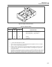
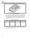
To provide easy access to the IEEE-488 Interface PCA and the Main PCA, the IEEE-488
Interface PCA can be placed in the specially provided service position as follows:
1. Remove the case from the chassis according to the Case Disassembly procedure
provided earlier in this section.
2. Release the two nylon latches that hold the IEEE-488 Interface PCA in place by
pulling the latches upward.
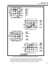
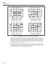
3. Position the IEEE-488 Interface PCA vertically as shown in Figure 6-19 and latch it
in place be pressing the two nylon latches into the mounting supports specially
provided on the chassis.
6-70. DIAGNOSTIC PROGRAM
To facilitate troubleshooting, the IEEE-488 Interface provides a diagnostic program
which places the instrument in known configurations. To initiate the diagnostic program,
proceed as follows:
CAUTION
To avoid damage to the 8842A or other equipment, the 8842A
must be disconnected from all other IEEE-488 Interface
instruments while the diagnostic program is running.
1. Ensure the 8842A POWER switch is OFF.
2. Disconnect all cables from the rear panel IEEE-488 connector.
3. Short TP903 to TP905.
4. Power up the 8842A. The 8842A should display ERROR 50. To exit the
troubleshooting mode, open the jumper and cycle the POWER switch from off to on.
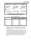
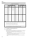
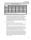
Once the diagnostic program is started, rear-panel IEEE-488 address switches A3, A2,
and A1 can be used to select one of four diagnostic modes, as shown in Table 6-24. In
this table, Configuration indicates which Out-Guard µC I/O port bits are programmed as
outputs and driven with a signal, as shown in Table 6-25.


