


8842A
Instruction Manual
6-36
WARNING
TO AVOID ELECTRIC SHOCK, ENSURE THAT
THE GROUNDING SCREW IS FIRMLY
ATTACHED TO THE CASE BOTTOM.
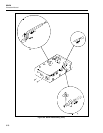
6-34. INTERNAL FUSE REPLACEMENT
CAUTION
For fire protection, use exact fuse replacements only.
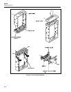
The 8842A has an internal 3A 600V slow-blow fuse (F301) in series with the 2A input
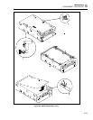
terminal. To replace this fuse, remove the case according to the disassembly instructions.
The fuse is held in fuse clips on the Main PCA. Do not use makeshift fuses or short-
circuit the fuse holder.
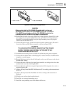
6-35. EXTERNAL TRIGGER POLARITY SELECTION (Option -
05 Only)
The EXT TRIG input is factory-configured with negative polarity (trigger on falling-
edge). This polarity is set by jumper E902 on the IEEE-488 Interface PCA. To select
positive polarity (trigger on rising-edge), remove jumper E902 and add jumper E903.
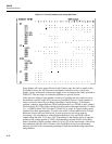
6-36. TROUBLESHOOTING
The 8842A is designed to be easily maintained and repaired. Both the analog and digital
circuits have built-in diagnostic self-tests and troubleshooting modes to facilitate
troubleshooting and repair. The instrument’s circuits allow troubleshooting and repair
with basic electronic troubleshooting equipment such as a multimeter and oscilloscope.
The troubleshooting mode in the digital controller circuitry generates special test signals
to allow troubleshooting and repair without a special test signal generator or complex
logic analyzer. Using the information in this section, a technician should be able to
troubleshoot and repair the 8842A very efficiently. There is also a troubleshooting
package available which utilizes the Fluke 9010A System Troubleshooter. The 8842A-
9000 Troubleshooting Kit is described in detail in Section 8.
6-37. Initial Troubleshooting Procedure
WARNING
TO AVOID INJURY OR EQUIPMENT DAMAGE, USE EXACT
REPLACEMENT PARTS FOR ALL PROTECTION COMPONENTS.
When a problem occurs in the 8842A, first verify the problem is actually in the
instrument. If the problem occurs when the instrument is in a system, check to see if the
same problem exists when under local control. Watch the display as the instrument is
turned on to see if any of the digital self-test error codes appear indicating a digital
failure. If the malfunction does not involve the True RMS AC or IEEE-488 options,
remove the option(s) from the instrument before proceeding.