Theory of Operation
POWER SUPPLY
5
5-25
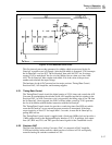
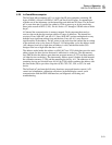
The circuit in Figure 5-15 has two stable states, corresponding to output high (+5V) and
output low (0V). If the output is high, the voltage present at the non-inverting input of op
amp A is approximately +140 mV.
Since the inputs to op amps A and B are inverted, their outputs are always in opposite
states. If the output of A is high, the output of B is low, forcing the inverting input of A
(and the non-inverting input of B) to ground, hence reinforcing the existing state. The
situation is analogous if the output of A is low.
A positive-going transition at the input causes a positive pulse at the non-inverting input
of A, and a corresponding negative pulse at the inverting input of A. If the output is high
to start with (with the non-inverting input of A raised 140 mV above its inverting input),
these pulses reinforce the existing state (raising the non-inverting input and lowering the
inverting input). If, however, the output is low to start with, the positive pulse (which is
greater than 140 mV) raises the non-inverting input of A above its inverting input,
switching the output to the high state. The situation is analogous for a negative-going
input transition.
5-36. POWER SUPPLY
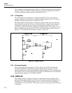
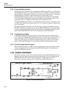
The Power Supply provides the following in-guard outputs: +/-30V, +/-15V, -6.2V,
+7.5V, +5V, -5V, and -8.2V dc; and 4.5V ac. The Power Supply also provides a 16V ac
center-tapped out-guard output.
Input line voltage is directed to the primary transformer winding through fuse F601, the
front panel POWER switch, and the rear panel LINE SET switches. Metal oxide varistor
RV601 clamps line transients at about 390V. The LINE SET switches configure the
Power Supply to accept line power of 100, 120, 220, or 240V ac (+/-10% with a
maximum of 250V) at 50, 60, or 400 Hz.
AC voltage for the +5V supply is rectified by CR601 and CR602 and regulated by
VR601. The +5V output supplies mostly logic circuits. The ac input to the +5V supply is
sensed by the In-Guard µC (via R604, CR615, and U221-12, 13) to measure the line
frequency.
AC voltage for the +30V and -30V supplies is rectified by bridge network CR603,
CR604, CR605, and CR606 and regulated by VR602 and VR605. The +30V and -30V
outputs supply front-end buffer amp U306. In addition, the +30V output supplies the
anodes of the vacuum fluorescent display. Zener diode CR612 supplies -6.2V to the A/D
Converter clamps.
AC voltage for the +15V and -15V supplies is rectified by bridge network CR608,
CR609, CR610, and CR611 and regulated by VR603 and VR604. The +15V and -15V
supply analog circuitry throughout the 8842A. Zener diodes CR613 and CR614 supply
+7.5V and -8.2V to the A/D Converter, analog filter, and DC Scaling circuit.
Secondary T601-14, 15, 16 supplies the vacuum fluorescent display filament with 4.5V
ac. The center tap is connected to the in-guard +5V supply in order to correctly bias the
display. An isolated secondary supplies 16V ac to the power supply on the IEEE-488
Interface.
Zener diode CR615 and SCR Q601 comprise a protective crow-bar circuit. If the line
voltage exceeds the nominal value by approximately 30 percent or more, CR615
conducts, turning on Q601, shorting out the power transformer secondary and blowing
the line fuse. In normal operation, these components have no effect.


