


8842A
Instruction Manual
6-40
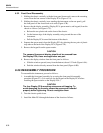
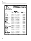
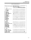
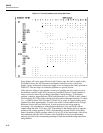
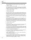
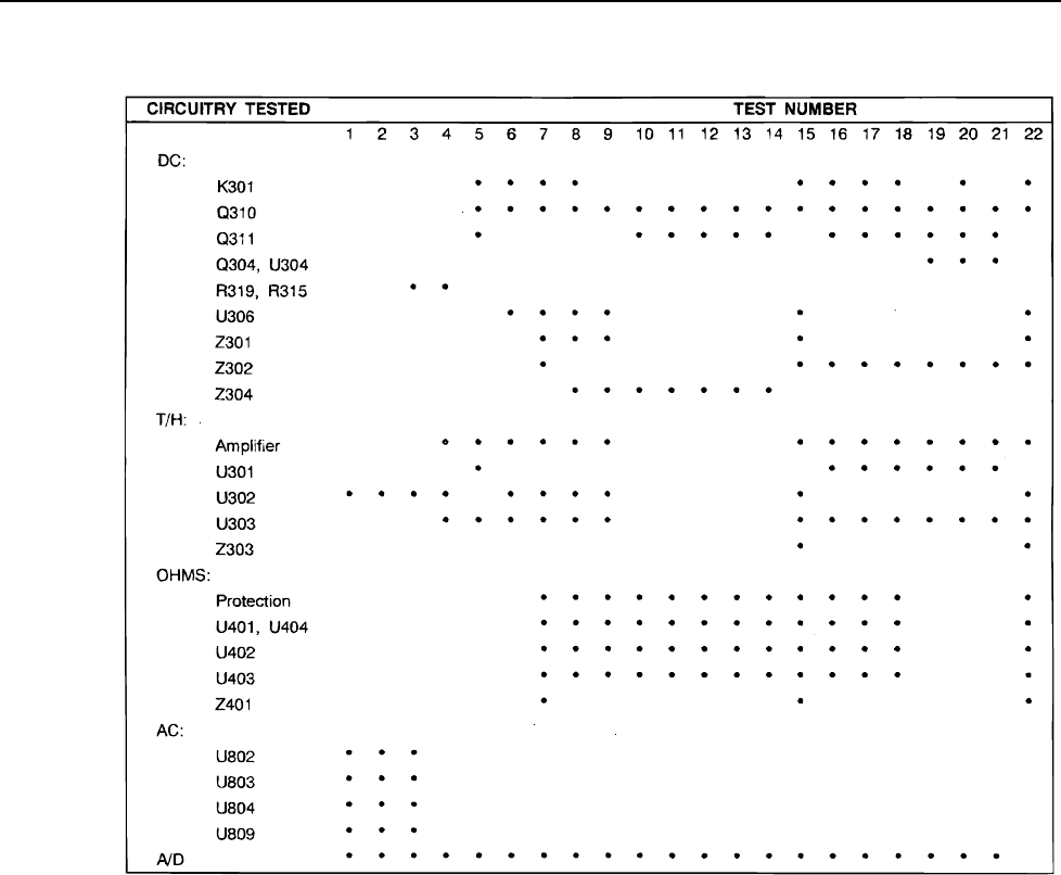
Table 6-17. Circuitry Tested by the Analog Self-Tests
t6-17.wmf
Some failures will cause many self-tests to fail. If this occurs, the fault is usually in the
Track/Hold circuit, the A/D Converter, the Digital Controller circuit, or the Power
Supply. Again, measure all of the power supply levels according to the limits specified in
Table 6-23. The next step is to isolate the problem to a specific section.
If the self-tests display a large number of errors or if readings are noisy and/or in error,
the problem is usually in the A/D Converter or Track/Hold circuit. (A large number of
errors can also be caused by a problem in the Ohms Current Source.) To isolate the
problem, connect a jumper between TP103 and Reference Low (TP306, or the L-shaped
shield around U202). The display should typically read less than approximately 35 counts
(i.e., +/-.000XX where XX is less than 35) on the 2V dc range. If a good reading can be
obtained (less than approximately 35 counts), the A/D Converter and Precision Voltage
Reference circuits are most likely good. A more conclusive test can be made by
connecting a low-impedance dc source between Reference Low and TP103 with an
output voltage between -2.0V and +2.0V. The reading on the display will be of opposite
polarity to the voltage applied to TP103. (Disconnecting one end of R318 will usually
make it possible to display readings within 0.1% to 0.5% of the actual input.) After it has
been determined that the A/D Converter or the Track/Hold circuit is not functioning
properly, proceed to the corresponding heading for detailed troubleshooting instructions
and guidelines.