


8842A
Instruction Manual
6-20
readings. (In remote calibration, the averaged value can be stored in the controller.)
Record the value.
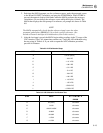
4. Select the "100Ω" output from the 5450A, and measure this value as in step 3.
5. Find and record the numerical difference between the values calculated in steps 3 and
4. This value will be used as the variable input for calibrating the 200Ω range in 2-
wire ohms.
6. Repeat steps 4 and 5 using the "1 kΩ" output from the 5450A; find and record the
numerical difference between this and the "SHORT" measured in step 3. This value
will be used as the variable input for calibrating the 2 kΩ range in 2-wire ohms.
7. Press the UUT’s 2 WIRE kΩ button. This selects the Offset and Gain calibration
procedure for the 2-wire ohms function and prompts for zero input. Select the
"SHORT" from the 5450A, and calibrate all the zeros by pressing STORE.
8. Select the "100Ω" output from the 5450A and calibrate the high point for the 200Ω
range, entering the value computed in step 5 as a variable input.
9. Select the "1 kΩ" output from the 5450A and calibrate the high point for the 2 kΩ
range, entering the value computed in step 6 as a variable input.
10. Calibrate the remaining ranges (steps D-G of Table 6-10) using the 5450A outputs.
11. Recalibrate the low point for each 2-wire ohms range using a shorting link (Pomona
MDP-S-0 or equivalent) across the UUT’s HI and LO INPUT terminals.
12. Exit the calibration mode by pressing the CAL ENABLE switch.
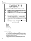
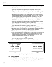
13. Using the same configuration shown in Figure 6-4, verify that the UUT measures the
same value (within 1 digit) in 2-wire ohms (using the offset feature to correct for
5450A floor error) as in 4-wire ohms. If the readings differ by more than 1 digit,
reenable the calibration mode and repeat steps 2 through 8.
NOTE
Only 4-wire ohm calibration is allowed in the 20
Ω
range.
14. Cover the CAL ENABLE switch with a calibration certification sticker.
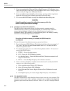
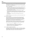
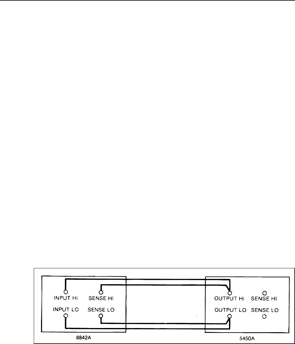
f6-04.wmf
Figure 6-4. Optimizing Use of the 5450A
6-23. Remote Calibration
If the IEEE-488 Interface is installed, the 8842A can be calibrated under remote control.
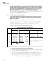
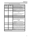
Remote calibration is very similar to local (front-panel controlled) calibration. Table 6-14
shows the remote commands which correspond to the front panel features.To facilitate
remote calibration, there are some differences from local calibration: