8842A
Instruction Manual
2-12
In the continuous trigger mode, the actual number of readings displayed per second for
each reading rate is determined by the line-power frequency. At power-up, the 8842A
senses the line-power frequency and adjusts the analog-to-digital converter timing
characteristics for optimum normal-mode noise rejection. The resulting reading rates are
shown in the specifications in Section 1.
2-21. Automatic Settling Time Delay
When the external trigger mode is selected, the 8842A automatically inserts a delay after
receiving a trigger signal, but before starting the first input sample. The delay is just long
enough so that the reading will be correct (within a specified number of counts of the
final value) even if the trigger signal occurs as the input makes a step change between
zero and full scale (10,000 counts and full scale in the ac functions).The length of the
delay depends on the range, function, and reading rate, as shown in the specifications in
Section 1. The delay is enabled only in the external trigger mode. It can be turned off
with a remote command over the IEEE-488 interface bus to accommodate special timing
considerations.
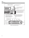
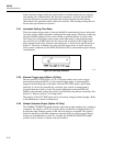
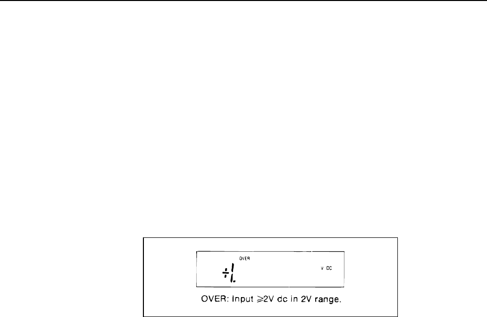
f2-08.wmf
Figure 2-8. Overrange Indication
2-22. External Trigger Input (Option -05 Only)
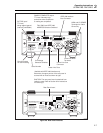
The rear panel EXT TRIG input is a TTL-level input which can be used to trigger
measurements when the 8842A is in the external trigger mode. A measurement is
triggered on the falling edge of the input. Since the EXT TRIG input is pulled high
internally, it can also be controlled by a normally open switch. A measurement is
triggered when the switch is closed. For special applications using the IEEE-488
Interface, the automatic setting time delay can be disabled using remote commands. (See
Section 3.) Refer to Section 1 for timing details.
The polarity of the EXT TRIG input can be reversed by changing internal jumpers. Refer
to the Maintenance section for instructions.
2-23. Sample Complete Output (Option -05 Only)
The SAMPLE COMPLETE output indicates when analog input sampling for a reading is
completed. The output is a TTL-level signal which is pulsed low for approximately 2.5
µs when the input-sampling portion of the A/D conversion is completed. The signal is
useful for interfacing with other equipment when the 8842A is used in external trigger
mode in an instrumentation system. For example, the SAMPLE COMPLETE output
could be used to advance a scanner to the next channel.


