Operating Instructions
MAKING MEASUREMENTS
2
2-13
2-24. MAKING MEASUREMENTS
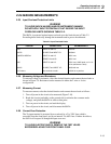
2-25. Input Overload Protection Limits
WARNING
TO AVOID SHOCK HAZARD AND/OR INSTRUMENT DAMAGE,
DO NOTAPPLY INPUT POTENTIALS THAT EXCEED THE INPUT
OVERLOAD LIMITS SHOWN IN TABLE 2-2.
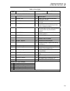
The 8842A is protected against input overloads up to the limits shown in Table 2-2.
Exceeding these limits may damage the instrument and/or pose a shock hazard.
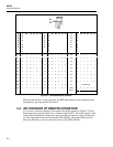
Table 2-2. Input Overload Limits
FUNTION CONNECTORS MAXIMUM INPUT
VDC INPUT HI and LO: 1000 dc
MA DC 2A INPUTand INPUT LO: 2000mA
2 WIRE/4 WIRE kΩ INPUT HI and LO: 300V rms
SENSE HI and LO: 300V rms
VAC INPUT HI and LO: 700V rms, 1000V peak, or 2 x 10
7
V-Hz (whichever is less)
MA AC 2A INPUT and INPUT LO: 2000 mA rms
All Funtions Any terminal to earth: 1000V dc or peak ac
2-26. Measuring Voltage and Resistance
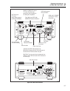
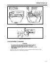
To measure voltage or resistance, select the desired function and connect the test leads as
shown in Figure 2-9. Resistance can be measured in either the 2-wire or 4-wire
configuration.
2-27. Measuring Current
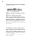
To measure current, select the desired function and connect the test leads as follows:
1. Turn off power in the circuit to be measured (Figure 2-10).
2. Break the circuit (preferably on the ground side to minimize the common mode
voltage), and place the 8842A in series at that point.
3. Turn on power in the circuit, and read the display.
4. Turn off power in the circuit, and disconnect the 8842A.
2-28. Current Fuse Protection
The 2A input terminal is protected from overloads by a 2A, 250V fuse which is
accessible from the front panel, and by an internal 3A, 600V fuse. If either fuse blows,
the 8842A will respond as though the input were zero.
WARNING
TO AVOID ELECTRIC SHOCK, REMOVE THE TEST LEADS
BEFOREREPLACING THE FRONT PANEL FUSE.


