


8842A
Instruction Manual
6-68
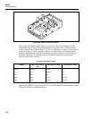
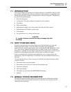
f6-20.wmf
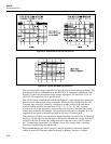
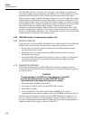
Figure 6-20. Option -09 Service Position
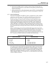
If the signal at the input to U801A (pin 5) is incorrect, U804 may be defective, or the
switch codes may be wrong. If the latter problem is suspected, refer to Table 6-28 and
test the control lines to U804 (U804-1, 8, 9, 16). If a logic error is found, it may be due to
excessive loading or a faulty data latch (U803), or other cabling or main-board digital
problems. High-frequency oscillation problems are usually caused by switches being on
when they should be off, resulting in positive feedback loops being closed around
portions of the scaling circuitry.
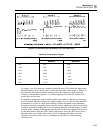
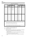
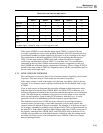
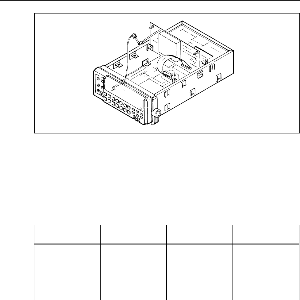
Table 6-27. AC Signal Tracing
RANGE INPUT VOLTAGE (1
kHz)
VOLTAGE AT TP801 VOLTAGE AT TP802
200 mV 100 mV 20 mV 1 V
2V 1V 200 mV 1 V
20V 10V 2V 1V
200V 10V 20 mV 100 mV
700V 100V 200 mV 100 mV
If the signal at TP802 is incorrect, but U801-5 is OK, the digitally controlled filter section
(U801A and U808) is probably defective.