


8842A
Instruction Manual
6-42
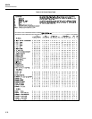
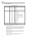
6-39. Self-Test Descriptions
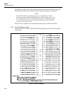
Table 6-18. Self-Test Voltages
TEST NUMBER TEST POINT VOLTAGE
1 TP803 ±5 mV dc
2 TP803 ±5 mV dc
3 TP803 ±5 mV dc
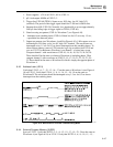
4 TP103 T/H output waveform for zero input (Figure 6-14)
5 TP302 ±5 mV dc
6 TP302 ±5 mV dc
7 TP302 +50 mV dc typical
8 TP302 +11.5V dc typical
9 TP302 +11.5V dc typical
10 TP302 +4.5V dc with possibly 1V ac (p-p) at 10 Hz
11 TP302 +4.5V dc with possibly 1V ac (p-p) at 10 Hz
12 TP302 +4.5V dc with possibly 1V ac (p-p) at 10 Hz
13 TP302 +4.5V dc with possibly 1V ac (p-p) at 10 Hz
14 TP302 +4.5V dc with possibly 1V ac (p-p) at 10 Hz
15,22 TP302 +50 mV dc typical
16 TP302 +49 mV dc typical
17 TP302 +53 mV dc typical
18 TP302 +59 mV dc typical
19 TP302 <±5 mV dc
20 TP302 +59 mV dc
21 TP302 <±5 mV dc
Note: To measure these correctly, each test must be stopped using the SRQ button.
Also use TP306 (or L-shaped shield around U202) as Reference low.
• TEST 1: 200 VAC, Zero
Configures the 8842A in the 200V ac range (except that K801 is opened) and measures
the open-circuit floor reading. In this range, the first and second stage buffers effectively
divide any noise at the input terminals by 100. This test should be fairly immune from
noise because the input terminals are always open-circuited except for capacitive
feedthrough across K801.
• TEST 2: 700 VAC, Zero
Configures the 8842A in the 700V ac range and measures the open-circuit floor reading.
In this range, the open-circuit reading is divided by 1000. Again, K801 is opened to
reduce sensitivity to external noise.
• TEST 3: mA AC, Zero
Configures the 8842A exactly as in the mA AC function and takes a reading of the
voltage across the 0.1Ω current shunt at the slow reading rate.
• TEST 4: mA DC, Zero